Wednesday, November 14, 2012

Timber Grillage Foundation.

Timber grillage foundation is provided for heavily loaded timber column or masonry wall. The foundation uses timber planks and timber beams in the place of steel joists. This foundation is specially useful in water logged areas where the bearing power of the soil is very low, and where the steel beams may get corroded due to subsoil water. The loading on the soil is limited to 50 to 60 kN/m2. No concrete is embedded between the timber joists. However, the bottom concrete (provided in steel grillage foundation is replaced by timber platform constructed of timber planks.

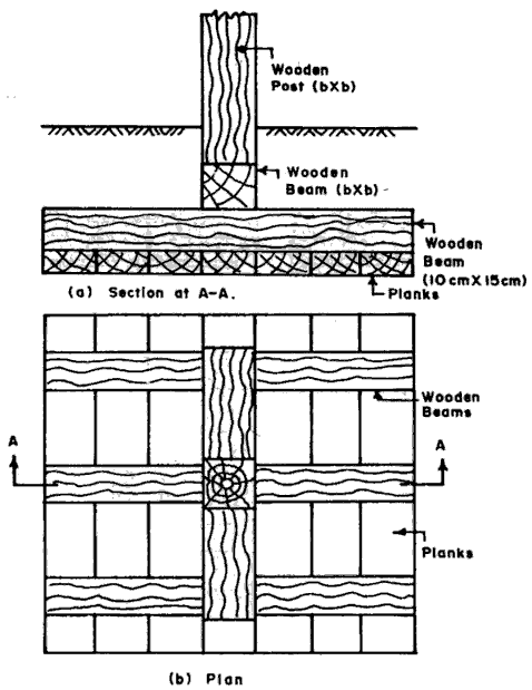
FIG. 3.12 TIMBER GRILLAGE FOUNDATION FOR WOODEN POST.
FIG. 3.12 shows a typpical timber grillage foundation for a timber column. After excavating the foundation of the desired depth an levelling it, the bottom layer of planks 5 to 7.5 cm thick and 20 to 30 cm wide is laid. The planks are arranged side by side, without any ga between them. Over this platform, a tier of wooden beams, about 15 cm x 10 cm in size, spaced 30 to 50 cm apart, is laid at right angles to the direction of the planks. Over the top of this layer, at timber beam of the same section as that of the wood post is placed at right angle. The timber post is then fixed at right angle to this timber beam.

FIG. 3.13 TIMBER GRILLAGE FOUNDATION FOR MASONRY WALL.
Fig. 3.13 shows the timber grillage foundation for a wall. The foundation consists of two layers of wood planks, separated by rectangular section (beams) of timber placed at right angles to the direction of the wall.

The upper layer of the planks, placed (side by side) may be 7.5 to 10 cm thick, extending over the full width of the wall base, and running longitudinally along the wall. The lower layer of planks may be 5 to 7.5 cm thick, placed longitudinally along the wall. However, the lower layer of timber planks, an also the middle tier of timber beams, should extend to atleast  45 to 60 cm on either side of the wall footing base.

Steel Grillage Foundation - Method of Construction.

Steel grillage foundation is constructed of steel beams, structurally known as rolled steel joists(RSJ.), provided in two or more tiers. In the case of double tier grillage(which is commonly provided), the top tier of grillage beams is laid at right angles to the bottom tier. The joists or beams of each tier are held in position by 20 mm diameter spacer bars wtth 25 mm diameter pipe separators. Fig. 3.10 shows the plan and section of such a foundation. The grillage beams are embedded in concrete. Generally, a minimum clearance of 8 cm is kept betwen the grillage beams so that concrete can be easily poured and properly compacted. However, the distance between flanges should not exceed 30 cm  or 1 ½  times the flange width (whichever is small) so that the filled concrete acts monolithically with the beams. It should be noted that the concrete filling does not carry any load; it simply keeps the beams in position and prevents their corrosion. A minimum concrete cover of 10 cm is kept on the outer sides of the external beams, as weIl as upper flanges of top tier. The depth of concrete below the lower tier should atleast be 15 cm.

Method of construction. The foundation is excavated to the desired depth. Generally, the depth of foundation is shallow, just sufficient to accommodate the two tiers of grillage beams and the gusset plates etc. connecting the stanchion to the base. Howeer this depth should not be less than 90 cm in any case. After leveling the foundation base, rich concrete is poured and compacted, so that the formed thickness is not less than 15 cm. Compaction should be done properly so that the layer of concrete becomes an impervious bed.

This would protect the steel joists against ground water. After levelling the concrete bed, first layer of grillage beams of designed sizes are laid over it, at proper distances, with the help of separaters. The upper surface of all the beams should lie in one horizontal plane. Rich cement grout is then poured all around the lower flanges of the beams so that they are secured to the concrete bed. Cement concrete is then poured betwecn and around the beams of the first tier. The second tier of beams is then placed at right angles to the first tier and over the top flanges of the beams of the first tier. They are properly spaced with the help of separators. Concrete is then poured between and around the steel beams. The steel stanchion is then connected to the upper tier with the help of a base plate, side angles and gusset plate. These connecting elements are also embedded in the concrete so that joint becomes rigid..

Steel grillage foundation may also be provided for a masonry wall on soils of low bearing capacity. The grillage foundation for such a case consists of only on tier, though in some circumstances when the wall is wider and it carries heavy loads, two tiers may also be provided. Fig. 3.11 shows the details for both the cases.

FIG. 3.10 TYPICAL GRILLAGE FOUNDATION FOR STEEL STANCHION.


FIG. 3.11 STEEL GRILLAGE FOUNDATIONS FOR WALLS.

GRILLAGE FOUNDATIONS.

A grillage foundation is a special type of isolated footing, generally provided for heavily loaded steel stanchions, specially in those locations where bearing capacity of soil is poor. The depth of foundation is limited from 1 m lo 1.5 m. The load of the column or stanchion is distributed or spread to a very large area by means of layers or tiers of joists, each tier being placed at right angles to the next tier. Grillage foundations are of two types:

1. Steel grillage foundation Steel grillage foundation is constructed of steel beams, structurally known as rolled steel joists(RSJ.), provided in two or more tiers. In the case of double tier grillage(which is commonly provided), the top tier of grillage beams is laid at right angles to the bottom tier. The joists or beams of each tier are held in position by 20 mm diameter spacer bars wtth 25 mm diameter pipe separators. Fig. 3.10 shows the plan and section of such a foundation. The grillage beams are embedded in concrete....
 

2. Timber grillage foundation. Timber grillage foundation is provided for heavily loaded timber column or masonry wall. The foundation uses timber planks and timber beams in the place of steel joists. This foundation is specially useful in water logged areas where the bearing power of the soil is very low, and where the steel beams may get corroded due to subsoil water. The loading on the soil is limited to 50 to 60 kN/m2. No concrete is embedded between the timber joists. However, the bottom concrete (provided in steel grillage...

ECCENTRICALLY LOADED FOOTINGS.

The footings are so designed and proportioned that the C.G. of the superimposed load coincides with the C.G. of the base area, so that the footing is subjected to concentric loading, resulting in uniform bearing pressure. However, in some cases, it may not be possible to do so. For example, if the wall (or column) under construction is near some other property, it will not be possible to spread the footing to both the sides of the wall or column. Such a situation is shown in Fig. 3.7.

FIG. 3.7 ECCENTRIC LOADING.
 
Let this resultant load have an eccentricity e with respect to the centre of base width B. This eccentric weight
is equivalent to (i) a centrally placed load W and (ii) bending moment M = W . e.

Due to these two, a trapezoidal soil pressure diagram, having pressure intensities q1 and q2 will result.

 The magnitude of q1 should not exceed the safe bearing pressure for the soil. Also in order that the footing may remain in contact with soil, q2 should be positive (i.e. no tension should be developed). In the extreme case, q2 = 0, when e = B/6. This gives the maximum value of eccentricity. In that case
average pressure on the foundation. If e is greater than B/6 tension will be developed, in which case, the end B of the footing will have loose contact with the soil.

Tuesday, November 6, 2012

Footings for Reinforced Concrete Columns.

Reinforced concrete columns are supported on reinforced concrete footings only. Fig. 3.6 shows typical details of such footings.

FIG. 3.6 REINFORCED CONCRETE FOOTINGS FOR R.C.C. COLUMNS.

Stepped Pad Footing.

If the column load is more, or if the safe bearing pressure of the soil is less, the base area found by Eq 3.5 will be large (much greater than b + 2a). In that case, it is necessary to provide masonry offsets, to achieve larger spread, before the load is transferred to the concrete base. The height and width of each offset shold be so proportioned that rate of spread does the stepped footing, in which the rate of spread is n : 1 for masonry an n1 : 1 for concrete, where n = 1/2 for masonry, and n1 = 2/3 for lime concrete an 1 for cement concrete.

In the case of brick pillar, the offsets should not exceed 5 cm. In the case of masonry pillar, the offset may vary between 10 to 15 cm corresponding to the step height of 15 to 22.5 respectively.

FIG. 3.5 STEPPED PAD FOOTING.

The depth of concrete block is given by


where q and m are in the same units (i.e. in kg/cm^2 or t/m^2 or kN/m^2), and d and a are in the same units
(i.e. in cm or m ro mm).

Simple Pad Footing.

If P is small, or qs is large, A will also be small. In tha case, the footing may consist of simple concrete block projecting out from the column face on all sides. The shape of the footing is generally kept the same as that for the column (i.e. trapezoidal square or circular), as illustrated in Fig. 3.4, so that equal projection (=a) is obtained for the base concrete.

FIG. 3.4 SIMPLE ISOLATED FOOTINGS OF LIGHTLY LOADED COLUMNS.


The value of offset a may vary from 10 to 20cm. As a thumb rule, the base dimensions of the concrete base should not be less than twice the appropriate lateral dimension of the column in that direction. The thickness of concrete block should atleast be equal to a in the case of cement concrete and 3/2 a in the case of lime concrete base.

ISOLATED FOOTING OR PAD FOOTING.

A spread footing for a single column is either known as the isolated footing or pad footing. The base area A such a footing is given by


where P is the total load transmitted by the column, including that of the footing an qs is the safe bearing pressure for the soil.

(a) Simple pad footing. If P is small, or qs is large, A will also be small. In tha case, the footing may consist of simple concrete block projecting out from the column face on all sides. The shape of the footing is generally kept the same as....

(b) Stepped pad footing. If the column load is more, or if the safe bearing pressure of the soil is less, the base area found by Eq 3.5 will be large (much greater than b + 2a). In that case, it is necessary to provide masonry offsets, to achieve....
 

(c) Footings for reinforced concrete colums. Reinforced concrete columns are supported on reinforced concrete footings

STRIP FOOTINGS: Depth of concrete bed block.

The depth of concrete bed block depends upon the type of concrete, the projection of the block and the soil bearing pressure. It is found on the basis of the bending moment imposed on it, and on the basis of safe modulus of rupture.


For a footing shown in Fig. 3.3 let

d = depth of concrete block in cm.
a = projection beyond the masonry face in cm.
m = safe modulus of rupture of concrete mix, in kg/cm^2.
q = net soil bearing pressure, in kg/m^2.

FIG. 3.3

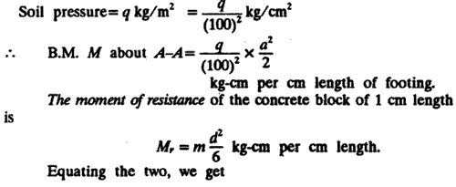
The projected concrete block will be subjected to bending moment due to upward soil presure q. The maximum B.M. will  be about plane A-A. Consider 1 cm length of the footing ( or wall ).


In the above expression, q and m are in the same units (KN/m^2) while d and a area also in the same units ( i.e. either in mtres or in cm or in mm).

Equation 3.4 (a) is also valid if both q and m are expressed in t/m^2 units.

The value of modulus of rupture m for various types of concrete are given in Table 3.2


TABLE 3.2 SAFE MODULUS OF RUPTURE OF CONCRETE.

Stepped Footing.

When the wall carries heavy loads, or when the safe bearing pressure of the soil is not very high, the base width required from Eq 3.2 wilI be much greater than (T + 2 a). In that case, it is essential to provide masonry offsets, to achieve larger spread, before the load is transferred to concrete base. The height and width of cach offset should be so proportioned that rate of spread does not exceed the permissible value for the masonry Fig. 3.2(b) shows such a stepped footing in which the rate of spread through masonry is n :1 and that through concrete base is n1 :1. 


The implication of the above recommendations is that  in order to spread the bearing width from original T (width of walI) to B (footing width), the minimum depth required would workout as follows: 


In the case of brick walls, the offset should not be greater than 5 cm; the corresponding height of each step would work out to be 10 cm. As a thumb rule, the width B’ of the bottom brick course should not be less than twice the width of the wall. In the case of stone masonry, the offsets may vary from 7 ½  cm to 10 cm(max.) corresponding to a mim. height of masonry course equal to 15 cm and 20 cm respectively.

Simple Strip Footing.

(Fig. 3.2 a) ,When the wall carries light loads or when the safe bearing pressure is very high, the width of the footing found from the above expression would be very small. In that case, a simple strip footing.such as the one shown in Fig. 3.2 (a) is provided. The wall directly rests on the concrete base, and no masonry offsets are provided since spread is not required. However, the concrete base should project out by value a on either side of the wall face, where the value of offset a may vary from 1O to 2O cm. As a thumb rule, the width of concrete base should not be less than twice the width of the wall. The thickness of concrete block should at least be equal to offset a in the case of cement concrete and 3/2 a in the case of lime concrete base.

FIG. 3.2 STRIP FOOTING FOR WALL.

FOUNDATIONS: STRIP FOOTINGS.

A strip footing is the one which provides a continuous longitudinal bearing. Thus a spread footing for a
continuous wall is called a strip footing. Fig. 3.2 shows two types of strip footings for a wall: (a) simple
strip footing without masonry offset and (b) strip footing with masonry offsets.

An offset is the projection of the lower step from the vertical face of the upper step.

The width if footing is found on the basis of safe bearing pressure for the soil, by expression.

where

W = Total super-imposed load on the base of the footing
qs = Safe bearing pressure.

(a) Simple Strip Footing. (Fig. 3.2 a)
(b) Stepped Footing.
     Depth of concrete bed block


FIG. 3.2 STRIP FOOTING FOR WALL.

Monday, November 5, 2012

DEPTH OF FOOTINGS - FOUNDATIONS.

The footings should be carried below the top (organic) soli, miscellaneous fill, abandoned foundation, debris or muck. If the top loose soil or fill is too deep, two alternatives may be used depending upon the relative economy and the time available :

(i) Removing the top soil directly below the footing and replacing it with lean concrete [Fig. 3.1 (a)]
(ii) Removing the top soil in an area larger than the footing and replacing it with compacted sand and gravel fill. The area of the compacted sand and gravel fill should be sufficiently large to distribute the footing load, as shown in Fig. 3.1 (b).

In either case, it is essential to reach the level of the strata which has the required bearing capacity adopted for the design of footing.

FIG. 3.1.

Sometimes, the top soil may be good and compact, and may have adequate bearing capacity. In that case it is desirable to keep the minimum depth of foundation given by Rankines formula: (Eq. 2.8)


Where Ø is the angle of repose, the values of which may be taken from Table 3.1.


Note: It is to be noted that q is the actual load intensity and not the safe bearing capacity of soil. Some times, the actual load intensity may be less than the safe bearing capacity of soil, requiring lesser mínimum depth. When footings are supported on very stiff soil, having very high safe bearing capacity, the minimum depth of foundation computed on the basis of safe bearing capacity would come out to be vcry large which is ridiculous. In such soils, the width of the footing (found from other considerations) would be larger than the one required from the bearing capacity considerations, thus giving rise to actual soil pressure lesser than the safe bearing capacity.


TABLE 3.1. VALUES OF UNIT WEIGHT AND ANGLE OF REPOSE.


The depth of footing should also be such that the rate or angle of spread of the load from the walI base to the outer edge of the ground bearing does not exceed the permissible value, as envisaged in Fig. 3.3(a).

Shallow Foundations - Introduction.

Foundations may be broadly classified under two heads:

(a) Shallow foundations
(b) Deep foundations

According to Terzaghi, a foundation is shallow if its depth is equal to or less than its width. A shallow foundation is also known as an open foundation, since such foundation is constructed by open excavation. Hence those foundations, which have depth even greater than its width, but are constructed by way of open excavation also come under ‘shallow foundations’. A shallow foundation is placed immediately below the lowest part of the super-structure supported by it.

The term footing is commonly used in conjunction with shallow foundations. A footing is a foundation unit constructed. in brick work, masonry or concrete under the base of a wall or column for the purpose of distributing the load over a large area.

From the point of view of design, footings are classified into four types:

1. Spread footing
2. Combined footing
3. Strap footing
and 4. Mat or raft foundation.

A Spread footing is the one which supports either one wall or one column. A spread footing may be of the followíng types:

1. Strip footing It is the spread footing for wall.
2. Pad footing. It is the isolated footing for a column.

When a spread footing supports the load of more than one column or wall, it is called a combined footing or strap footing. A mat foundation is a foundation unit continuous in two directions covering an area equal to or greater than the base area of the building.

EXCAVATIONS: Electro-osmosis method.

This method is used for fine grained cohesive soils (such as clay), which can be drained or stabilised using electric current. The method was developed by L. Casagrande (1952). If direct current is passed between two electrodes driven into natural soil mass, the soil water will travel from the positive electrode (anode) to the negative electrode (cathode). The cathode is made in the form of well point or metal tube for pumping out the seeping form of well point or a metal tube for pumping out the seeping water. A steel rod, a pipe or steel piling of excavation can serve as the cathode. The arrangement of electrodes is done in such a way that the natural direction of flow of water is reversed away from the excavation, thereby increasing the strength of the soil and stability of the slope (Fig 2.41).

The potentials generally used in the process are from 40 to 180 volts, with electrode spacing of 4 to 5 metres.

FIG. 2.41 ELECTRO-OSMOTIC DRAINAGE.

EXCAVATIONS: Vacuum method: Forced flow.

The above methods are effectíve only in coarse grained soils. For fine grained solis, the welI point system can be extended by the vacuum method. For successful dewatering in the fine, non-cohesive soils, such as silty sands and other fine sands, it is neccesary to apply a suction head to the dewatenng system. Both the well point system and deep well system can be adopted for dewatering such soils by maintaining a vacuum in the well with the use of air tight seals for all points. A hole of about 25 cm diameter is created around the well point and the rise pipe by jetting water under sufficient pressure. While the jetting water is still flowing, medium to coarse sand is rapidly shovelled into the hole to fill it upto about 0.75 or 1 m from the top. The top portion of the hole is then sealed up by tamping bentonite, soil cement or clay (Fig. 2.40). Vacuum pumps are used to create vacuum in yhe sand filling. When the vacuum is drawn on the well point, the ground surface is subjected to unbalanced atmospheric pressure. Although the quantity of water drawn out does not increase much, the unbalanced atmospheric pressure acting on the ground surface consolidates the sub-soil which becomes stiff enough for carring out excavations.

 FIG. 2.40 VACCUM METHOD.

EXCAVATIONS: Deep well system.

When the depth of excavation is more than 16 m below the water table, deep well drainage system may be used with advantage. The system is also useful where artesian water is present. A 15 to 60 cm diameter hole is bored and a casing with a long screen (5 to 25 cm) is provided. A submeisible pump with a capacity to

push the water upto a height of 30 m or more is installed near the bottom to the well. Each well has its own pump. Along with the deep wells arranged on the outer side of the area under excavation, a row of well points is frequently installed at the toe of the side slopes of the deep excavation.

 FIG  2.39  DEEP WELL SYSTEM.


EXCAVATIONS: Shallow well system.

In this system, a hole of 30 cm in diameter or more is bored into the ground to a depth not excceding 10 m below the axis of the pump. A strainer tube of 15 cm diameter is lowered in the bore hole having a casing tube. A gravel filter is formed around the strainer tube by gradually removing the casing tube and simultaneousty pouring filter material, such as gravel etc. in the annular space. A suction pipe is lowered into the filter well so formed. The suction pipes from a number of such wells may be connected to one common header leading to the pumping unit.

EXCAVATIONS: Well point system.

A more complicated dewatering system based on gravity flow is the installation of well points. A well point is a perforated pipe, about ½ to 1 m long and 5 to 8 cm in diameter, covered by cylindrical wire gauge screen. In an expensive type well point, the steel tube is covered with two brass screens, the inner of fine mesh and the outer perforated (Fig. 2.36). A conical steel drive point is attached to the lower end of the pipe, with a neoprine ball valve fitted in the point to allow jetting of water to pass through it for driving it. When operating on suction, the ball is in the position shown and the soil water enters the outer screen, through the mesh, and down the flutes of the inner tube. Holes near the bottom of the latter and just above the shoe admit water to the inside where it is drawn up the riser, along the header to the pump for discharge through the pipes to a drain.

FIG. 2.36  DETAILS OF WELL POINT.


FIG. 2.37 LOWERING OF WATER TABLE BY WELL POINT SYSTEM.


The well points are placed in a row or ring, and the riser pipes are attached through a common manifold or header pipe to a special well point pump (Fig. 2.37). For inserting yhe well point into ground by jetting, water is pumped down the well point under pressure from where it emerges with a great velocity through the tip of the drive point. The emerging jet-stream dislodges the surrounding soil and the well point can be lowered to the desired depth. A further advantage of jetting is that water under pressure washes away soil fines from around the well point leaving a relatively coarser material lo settle and form a natural filter around the well point. The hole formed around the riser pipe and the welI point by jetting water is filled with coarse sand. The sand also helps in directing drainage to the well point.

The suction pump used in the well point system has a capacity of bringing water to the surface from a maximum depth of about 6 m. The well points are generally spaced between 1 to 2 m. For dewatering excavations which are more than 6 m below the water table, a multi-sage well point system (Fig. 2.38) is used. Excavations exceeding 16 m depth are preferably drained by deep well system. In the multi-stage well point sysem, the ground is first stripped to the natural water level where the first stage of well points is installed. After excavating about 5 m, second stage is installed to further lower the water table for advancing excavations. The other stages are put successively, upto a maximum depth of 16 m is reached. In the well point system, a round the dock pumping schedule is essential, as the interruption in pumping can have catastrophic consequences. Hence one auxiliary pumps for each two pumps is use should always be available.

 FIG. 2.38 MULTI-STAGE WELL POINT SYSTEM.
EXCAVATIONS: Ditches and Sumps.

This is the simplest form of dewatering used in shallow excavations in coarse grained soils. Shallow pits, called sumps are dug along the periphery of the area-drainage ditches. The water from the slopes or sides flows under gravity and is collected in sumps from which it is pumped out [Fig. 2.35(a)]. If the seepage (ie. flow of water) is significant, it may cause softening and revelling or sloughing of the lower part of the slope. There is also possibility of piping in the sump bottom, because of upward flow. In such circumstances, the sump can be weighted down with an inverted filter consisting of layers of successively coarser material from the bottom of the sump-pit upwards [Fig. 235(b)].

FIG. 2.35 EXCAVATION DRAINAGE WITH SUMP.