Showing posts with label CONCRETE. Show all posts

Monday, May 22, 2023

Cement Hydration and Concrete Curing

Cement Hydration and Concrete Curing Concrete curing is not simply a matter of the concrete hardening as it dries out. In fact, it is just the opposite. Portland cement is a hydraulic material. That is, it requires water for curing and can, in fact, fully cure to a hardened state even if it is completely submerged in water. Portland cement is anhydrous—it contains no water or moisture at all. The moment it comes in contact with water, a chemical reaction takes place in which new compounds are formed. This reaction is called cement hydration. The rate of hydration varies with the composition of the cement, the fineness of the cement particles, the amount of water present, the air temperature, and the presence of admixtures. If the mixing water dries out too rapidly before the cement has fully hydrated, the curing process will stop and the concrete will not harden to its intended strength. Curing will resume if more water is introduced, but at a slower rate. Hydration occurs more rapidly at higher air temperatures Cement hydration itself generates heat, too. This heat of hydration can be helpful during cold-weather construction, and potentially harmful during hot-weather construction. The chemical reaction between water and cement first forms a paste which must completely coat each aggregate particle during mixing. After a time, the paste begins to stiffen or set, and after a few hours has lost is plasticity entirely. The rate of this setting, however, is not the same as the rate of hardening. A Type-III high-early-strength cement may set in about the same time as a Type-I general-purpose cement, but the Type III hardens and develops compressive strength more rapidly after it has set.


Concrete normally cures to its full design strength in 28 days. Curing is slower in cold weather, and at temperatures below 40°F, the concrete can be easily and permanently damaged if it is not properly protected. Concrete must be kept moist for several days after it is placed to allow the portland cement in the mix to cure and harden properly. Concrete that is not kept moist reaches only about 50% of itsdesign strength. The Figure shows the differences in concrete strengthfor various periods of moist curing. If it is kept moist for at least three days, it will reach about 80% of its design strength, and for seven days, 100% of its design strength. If the concrete is kept moist for the full 28- day curing period, it will reach more than 125% of its design strength.



Thursday, September 1, 2022

Concrete Mix Designs

For work requiring more than one cubic yard of material, concrete is usually ordered from a ready-mix supplier for delivery to the job site. The supplier will need to know the minimum compressive strength, the maximum aggregate size, and any special requirements such as air entrainment for added freeze-thaw durability. The supplier will then select a mix design that is appropriate for your needs. If you are mixing small batches of concrete on site, you will need to understand the basic principles of concrete mix design yourself. The proportion of dry ingredients and the ratio of water to cement are the two most important factors.


Cement and aggregates provide strength, durability, and volume stability in concrete, but too much or too little of one in relation to the other reduces quality.


■ Lean or oversanded mixes with low cement content and high aggregate proportions are harsh and have poor workability.

■ Fat or undersanded mixes with high cement content and low aggregate proportions are sticky and expensive.


Within the range of normal concrete strengths, compressive strength is inversely related to water content. That is, the more water you use, the lower the concrete strength. But increasing water content increases fluidity and workability. Since water is required for workability, and since workability is required for high-quality concrete, the low water requirements for strength and high water requirements for workability must be balanced. The ratio of water to cement is the weight of water divided by the weight of cement. Water-cement ratio affects the consistency of a concrete mix. The consistency, in turn, affects how easily the concrete can be poured, moved around in the forms, compacted, and finished. Up to a point, a mix with more water is easier to work with than one that has less water and is therefore stiffer. Too much water, though, will cause the ingredients to separate during the pouring, placing, and handling and will destroy the integrity of the concrete. Too much water also lowers strength, increases the porosity and water permeability of the cured concrete, and makes it more prone to shrinkage cracking. The trick is to use enough water to make the fresh concrete workable, but not so much that it creates weak or porous structures.


Air content for ready-mix concrete should generally be 3 to 6-1/2%, depending on the maximum aggregate size (see Figure below). Concrete that is batched on site can be made with either an air-entrained cement or an air-entraining admixture. Using an air-entrained cement will yield an air content within the proper range. When using a separate airentraining agent, carefully follow the manufacturer’s instructions to determine the correct amount to add to the mix. For job-site mixing, air-entrained cement is usually easier to work with.


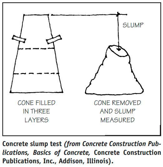
It is easier to measure concrete consistency or slump than to calculate water-cement ratio. The concrete mix consistency produced by adding various amounts of water is measured by slump tests in which fresh concrete is poured into a special mold called a slump cone. You can buy one from a building supply yard. Place the concrete into the cone in three layers. Tamp each layer with a metal rod to assure that it is completely consolidated and does not contain air pockets. When the cone is full, scrape off any excess concrete, leaving a level top. Then remove the cone and measure the amount of slump or settlement with a rod and ruler (Figure 2-11). The wetter the mix, the higher the slump measurement, and the drier the mix, the lower the slump measurement. The slump recommended to assure proper water-cement ratio for residential concrete is 3 to 5 inches. Slump tests can also be used to ensure consistent mixes from batch to batch.


As a general guideline for ordering ready-mix concrete, Figure 2-12 shows recommended mix requirements for various exposure conditions. The weathering regions indicated on the map are intended only as a guide. Particularly in mountainous regions, local conditions can change within a very short distance and may be more or less severe than indicated by the region classification. Severe exposures are those in which deicing salts are used because of significant snowfall combined with extended periods in which natural thawing does not occur. If you are in doubt about which classification applies, always use the more severe exposure. Actual concrete ingredient proportions can be measured either by volume or by weight.


Monday, February 11, 2013

Concrete Piles.

Concrete piles are the most widely used in the developed countries and may be cast in situ, precast, reinforced and prestressed.

(a) Precast
This type is commonly used where:

(i) The length required can be realistically predicted.
(ii) Lateral pressure from a stratum within the soil profile is sufficient to squeeze (neck) a cast-in-situ pile.
(iii) Where there are large voids in sections of the soil which would possibly have to be filled with an excessive amount of in situ concrete or could cause loss of support for wet concrete prior to setting.
(iv) For structures such as piers and jetties above water level on coastal, estuary and river sites.

Though precast piles can be manufactured on site it is  more common to have them designed, manufactured and installed by specialist subcontractors.

There are disadvantages in the use of precast concrete piles as follows:

(i) It is not easy to extend their length.
(ii) They are liable to fracture when driven into such obstacles as large boulders in boulder clay and the damage can remain out of sight.
(iii) Obstructions can cause the pile to deflect from the true vertical line.
(iv) There is an economic limit, restricted by buckling, of the unrestrained length of the pile.
(v) Noise and vibration caused by driving can cause nuisance and damage.
(vi) There can be large wastage and health and safety risks to the workforce caused by noise and vibration due to the need to cut off the projecting length after driving.
(vii) The accuracy of the estimated length is only proved on site when short piles can be difficult to extend and long piles can prove to be expensive and wasteful.
(viii) The relatively large rig required for driving often needs extensive hard-standings to provide a suitable surface for pile driving.

The advantages of precast concrete piles are:

(i) It is easier to supervise the initial quality of construction in precast than in situ.
(ii) The pile is not driven until the concrete is matured.
(iii) Stresses due to driving are usually higher than those due to foundation loading so that manufacturing faults are more easily discovered and, in effect, the  pile is preload tested (provided the defects can be detected).

The reinforcement, while adding to the load-bearing capa- city, is mainly designed to cope with handling, transporting and driving stresses.

(b) Cast in situ
There is an ever increasing variety of cast in situ piles offered by specialist piling subcontractors. The piles are
usually circular in cross-section and are regarded as small- diameter piles when their diameters are from 250–600 mm and larger-diameter piles when their diameters exceed  600 mm; large-diameter piles are now possible with dia- meters up to 3.0 m.

The advantages of cast in situ piles are:

(i) They can be constructed immediately, thus cutting out the time required for casting, maturing and delivering of precast piles.
(ii) There is no need to cut off or extend excessive lengths of the piles as they can be cast in situ to the required level.
(iii) They can be cast to longer lengths than is practical with precast piles.
(iv) Most obstructions can be hammered and broken through by the pile-driving techniques.
(v) The placing can cause less noise vibration and other disturbance compared to driving precast piles.
(vi) Soil taken from boring can be inspected and compared with the anticipated conditions.

The disadvantages of cast in situ piles are:

(i) It can be difficult to place and ensure positioning of any necessary reinforcement.
(ii) Concrete quality control is more difficult.
(iii) There is a danger of necking from lateral earth pressure.
(iv) Young concrete is susceptible to attack from some soil chemicals before it has set and hardened.

(c) Prestressed
Prestressed concrete in superstructure design is made of higher strength concrete, requires smaller cross-sectional area and can be made impact-resistant. The same results apply to prestressed piles relative to comparison with pre- cast reinforced piles. Their advantages compared to precast reinforced are:

(i) Handling stresses can be resisted by a smaller cross- section which can result in a more economical pile.
(ii) It is easier with the smaller section to achieve longer penetration into load-bearing gravels.
(iii) Tensile stresses that are generated up from the toe of the pile after the hammer blow can be compensated for by prestress.
(iv) The reduction of tensile cracking of the concrete can lead to greater durability.

The disadvantages of prestressed piles are:

(i) The smaller section provides less end bearing and total peripheral skin friction.
(ii) Deeper penetration into end-bearing strata (gravel, compact sand, etc.) may be necessary.
(iii) It is more difficult to extend the length of a precast driven pile.
(iv) As in prestressed concrete superstructure elements, stricter quality control in manufacture is necessary.

Wednesday, January 9, 2013

Design Decisions - Sizing up of the Design - Reinforced Concrete Pads and Strips..

Design decisions
The decision to reinforce a concrete foundation of this type usually follows the realization that the ground conditions are variable and/or deep trench fill is uneconomic.

Reference to (Table 10.2 Foundation selection to suit varying site conditions) on choice of foundation types will assist in this decision.

Sizing up of the design
The depth and width of the reinforced concrete strips are determined in a similar way to that adopted for unreinforced strips and trench fill. The depth to the underside of the footing is determined by the ground conditions and the level of suitable sub-strata, taking into account the need to be below the effect of any critical frost heave or swelling and shrinkage of sub-strata.

The fabric reinforced strip is used generally where there is both relatively poor ground and smallish loads or where some slight movements are expected from differential  settlement or subsidence.

More heavily reinforced strips, using bars and not fabric, are used where ground conditions are more critical and/or loading more excessive (see Fig. 11.21).


Fig. 11.21 Section through reinforced strip.

For particularly heavy loads and/or poor ground, beam strips are often used.

For axially loaded strip foundations, the breadth of the strip required is:
where P is the superstructure load/unit run and na is the net allowable bearing pressure.

The thickness of the foundation should be determined by designing for the cantilever action of the strip taking into account the bending, shear and bond stresses to be accommodated and allowing for the longitudinal moments and forces (see Fig. 11.20 Reinforced concrete strip design conditions.).

For strip footings a generous thickness for bending is  necessary in order to maintain the shear and bond stresses within permitted limits and in order to produce an economic balance for the ratio of concrete to reinforcement.

The detailed design of a reinforced concrete strip is covered in Design Example 3 which follows, but in general the  calculated foundation thickness required for shear and bending compression is rounded up to the nearest 50 mm as the economic thickness for the strip foundation.

Reinforced Concrete Pads and Strips.

Introduction
These pads are used in similar locations to those of the mass concrete pad, but where the reduction in cost of mass concrete exceeds the cost of the additional labour and materials.

These extras would include providing the reinforcement and any extra shuttering, blinding, or working space which may prove necessary for the reinforced solution.

The plan size and shape is determined from the vertical load and allowable bearing stress in conjunction with any physical requirements. The depth and amount of reinforcement is determined from the resulting bending moments and shear force considerations (see Fig. 11.20) or from  past experience. The experience basis is often used where reinforcement needs are related to variable ground for a familiar location and use or where there is a need to  cater for a number of time-related variations in differential settlement.


1 Design decisions and Sizing up of the design   Design decisions The decision to reinforce a concrete foundation of this type usually follows the realization that the ground conditions are variable and/or deep trench fill is...

2 Design Example 3: Reinforced strip foundation   The load-bearing wall of a single-storey building is to be supported on a wide reinforced strip foundation. A site investigation has revealed loose-to-medium granular soils...

3 Design Example 4: Reinforced pad base  The axially loaded pad base in Design Example 2 is to be redesigned as a reinforced base, founded in the weathered sandstone. Assuming settlements have been judged to be...


Reinforced concrete strip design conditions.
Fig. 11.20 Reinforced concrete strip design conditions.

Unreinforced Concrete Strips.

The unreinforced strip footing requires slightly better ground conditions than trench fill to maintain trench stability during construction of the masonry over it.

The adoption of a thin strip means that the trenches tend to remain open longer during construction than in the case  of the trench fill solution to allow bricklayers or masons to work from within the trenches. However, the overall cost of the work often proves less than for trench fill and on many sites proves to be easily achieved. It has the added advantage of more easily accommodating services but suffers  similar disadvantages to trench fill in active mining areas.

The choice between trench fill and concrete strips usually depends upon cost.

The width of the strip is generally the nearest suitable excavation standard bucket width to that of the design
width required from the calculations. However, for deep strips the working space required for bricklayers can  determine the width required. The thickness is generally selected to be greater than the overhang (i.e. this is based upon a 45° dispersion of load through the mass concrete, see Fig. 11.18).

 Fig. 11.18 Unreinforced strip.

Where this guidance would give a thinner strip than that practical from a construction point of view, or that desirable from a performance requirement, a greater nominal thickness is used. Longitudinal bending considerations, particularly where the strip requires to be continuous below door openings etc. (see Fig. 11.19), is one of the situations which may demand a thicker strip than that given  by the general 45° line. However, this would only apply if dispersion of load along this length of footing is required to reduce the bearing pressure.

Fig. 11.19 Continuous strip through opening.

Design Example: Deep Mass Concrete Pad Base.

A steel-framed building is to be built on a site adjoining previously, where variable fill extends down to the level of the bedrock. A heavily loaded stanchion, carrying axial load only, is to be supported on a pad foundation.

It has been decided to found the heavily loaded base in the sandstone bedrock, in order to minimize settlement. The base is to be constructed as a mass concrete pad.

Loadings
The superstructure working loads are as follows:


Allowable bearing pressure
From Design Example, the sandstone has a net allowable bearing pressure of na = 2000 kN/m2
.
Size of base
The foundation surcharge due to the groundbearing slab is small and can be neglected. Therefore,


Therefore a 1.5 m × 1.5 m pad foundation will be used, as shown in Fig. 11.15.

The stanchion bases are set at a common depth of 300 mm below slab level, and the remaining depth of excavation down to the sandstone rock is taken up by the mass concrete base.

The minimum depth of base required, before it becomes necessary for reinforcement to be introduced, is 500 mm (see depth to angle of load dispersion in Fig. 11.15). Clearly a mass concrete base is adequate in this instance.


Fig. 11.15 Mass concrete pad base design example.

The choice between the full sized mass concrete pad and the stub column solution is determined from economic  considerations.

The economic change-over point is where the cross-section required for groundbearing purposes becomes excessively wasteful in terms of the cost of concrete compared with the cost of introducing shuttering to form the smaller crosssection. Situations where this would apply are:

(1) Where the pads are very deep,
(2) Where the allowable groundbearing pressures are very low, or
(3) Where, due to the nature of the ground, a shuttered pad is required in any case.

The lower pad plan size is determined from the loading  and the allowable groundbearing capacity. If the section is reduced at higher level, the size at the point where it is reduced is generally based upon a 45° dispersion of load through the mass concrete (see Fig. 11.16).

Fig. 11.16 Stub column pad base.

The upper pedestal cross-section is determined from the load, the allowable bearing stress below the base plate and the allowable compressive stress on the mass concrete  in conjunction with a suitable practical and economic size for construction. For example, the size determined from stress considerations often needs to be rounded up to a larger practical mass concrete cross-section particularly where the mass pier is relatively tall (see Fig. 11.17).

Fig. 11.17 Mass pier criteria.

Unreinforced Concrete Pads and Strips.

In general, shallow pads and strips are the economic foundation for most structures where ground conditions allow this solution.

The suitability of shallow strips and pads should be one of the first considerations for the engineer and their use tends to form the  normal  foundation criteria against which the extra over cost of abnormal foundations tends to be judged.

This does not mean however, that strips and pads should be used wherever possible since as they become deeper or more heavily reinforced the alternatives of vibrocompaction and/or piles becomes competitive.

However, at shallow depth, they are the economic alternative.

1 Trench fill   A brief description of trench fill strips is given previously. The design of such strips is relatively simple, and it is true to say that there is more design involved in making the decision to

2 Trench fill design decisions   A typical trench fill foundation is shown in Fig. 11.7 where (a) indicates a typical section, (b) shows the typical design forces, and (c) illustrates the possible externally applied ground...

3 Sizing of the design   In the case of mass concrete trench fill the foundations can be sized using the assumptions that dispersion of load through the strip can be assumed to be at an angle of 45°. In the case...

4 Design Example 1: Trench fill strip footing   The internal load-bearing wall for a four-storey office block is to be supported on a strip foundation. Borehole investigations produced the consistent soil profiles shown in Fig. 11.13. Soil...

5 Design Example 2: Deep mass concrete pad base   A steel-framed building is to be built on a site adjoining previously, where variable fill extends down to the level of the bedrock. A heavily loaded stanchion, carrying axial load only, is to be supported on a...

6 Unreinforced concrete strips   The unreinforced strip footing requires slightly better ground conditions than trench fill to maintain trench stability during construction of the masonry over it. The adoption of a thin...

Monday, December 31, 2012

Concrete Piles - Uses.

Concrete piles are generally used to transfer loads through an unsuitable bearing material to a deeper load-bearing strata. This is achieved either by skin friction and end bearing or end bearing alone (see Fig. 9.34).

There are many different types and systems of piles,  however the main types are:

(1) Driven precast piles.
(2) Driven cast in situ piles.
(3) Bored piles.
(4) Augered piles.

These piles can also be divided into either displacement or replacement methods dependent on the system of driving, i.e. either removal of material, termed  replacement, or  wedging apart of material, termed  displacement. Typical examples of these types are shown in Fig. 9.35.

Fig. 9.34 Typical concrete pile.


Fig. 9.35 Concrete pile types.

Wednesday, December 19, 2012

Deep Mass Concrete Pads.

Deep mass pads consist of mass concrete pads cast with their soffit at depths in excess of 1.5–2 m. They are generally used where a suitable ground bearing strata is relatively deep and where the piling alternative is more expensive, i.e. a small number of pads are required or access for piling is difficult and expensive. Deep mass pads tend to be of two types, one being constructed up to high level using a basic cross-section and the other using a reduced and shuttered cross-section for the upper levels (see Fig. 9.14).

An alternative to concrete for the upper reduced crosssection is to construct a brick pier off the mass concrete pad (see Fig. 9.15). This solution has the advantage of avoiding the need for expensive shuttering and can result in an overall saving. If brickwork is adopted it is necessary that the pad size provides the necessary working space for the bricklayers to build the pier.

Fig. 9.14 Deep mass concrete pad.


Fig. 9.15 Deep mass concrete pad with brick pier.

Deep Reinforced Concrete Pads.

Deep reinforced concrete pads are similar in cross-section to the shallow reinforced pad but are constructed at depth in situations where the suitable sub-strata is not available  at high level. Such pads are not often economic and more cost-effective mass concrete bases or piles and caps are often used. However in some situations they can prove  to be a suitable solution – see Fig. 9.13 which indicates a typical example of such a use.

Fig. 9.13 Deep reinforced concrete pad.

Shallow Reinforced Concrete Pads.

Reinforced concrete pads are similar to the mass concrete pads but for the same conditions can be thinner when reinforced with steel. The reduction in thickness is made possible by the introduction of reinforcement on the tensile face of the pad which increases the pad’s resistance to bending moment (see Fig. 9.12).

Fig. 9.12 Shallow reinforced concrete pad.

Concrete Trench Fill.

Concrete trench fill consists of a mass concrete strip cast into the open trench making use of the trench sides as a shutter (see Fig. 9.5).

Concrete trench fill is often used where strip loads are required to be transferred to relatively shallow depths
through soft material which is capable of standing up, without extra support, for at least a period adequate to cater for the construction sequence to be adopted. The trench fill can embrace requirements for heavy loads going down to rock or light loads on soft sub-strata (see Fig. 9.6).

The requirement for working space within the trench  for bricklayers is not a factor in determining the width of excavation with this method. Pouring concrete to within 150 mm of ground level overcomes this consideration.

Fig. 9.5 Concrete trench fill.


Fig. 9.6 Concrete trench fill.

Concrete Strips – Plain and Reinforced.

The concrete strip footing replaced the corbelled masonry in more recent constructions. In plain (unreinforced) strip footings the thickness is determined by the requirement for the line of dispersion to pass through the side of the footing as shown in Fig. 9.1. The width of the trench must also allow working space for the bricklayers to build the masonry off the footing.

The profile of the reinforced concrete strip is similar to the unreinforced strip except that it can generally be made thinner in relation to its projections since it no longer relies upon an approximate 45° line of load dispersion. The strip is often reinforced with a fabric or lattice reinforcement.

The longitudinal bars are the main bars selected to suit the longitudinal bending expected on the strip and the cross bars designed to cater for the cantilever action on the projections (see Fig. 9.4).

Fig. 9.1 Typical strip footing.

Fig. 9.4 Reinforced strip footing.

Wednesday, December 5, 2012

CONCRETE RETAINING WALLS.

INTRODUCTION
The lateral pressure theories and the methods of calculating the lateral earth pressures were described in detail in the same chapter. The two classical earth pressure theories that have been considered are those of Rankine and Coulomb. In this chapter we are interested in the following:

1. Conditions under which the theories of Rankine and Coulomb are applicable to cantilever and gravity retaining walls under the active state.
2. The common minimum dimensions used for the two types of retaining walls mentioned above.
3. Use of charts for the computation of active earth pressure.
4. Stability of retaining walls.
5. Drainage provisions for retaining walls.

Saturday, November 17, 2012

Precast Concrete Piles.

These piles include conventionally  reinforced concrete piles and prestressed concrete piles.  Reinforced concrete piles are constructed with an  internal reinforcement cage consisting of several longitudinal bars and lateral ties, individual hoops, or a spiral. Prestressed concrete piles are constructed using steel rods or wire  strands under tension as reinforcement.  Since the concrete is under continuous compression, transverse cracks tend to remain closed; thus, prestressed piles are usually more durable  than conventionally reinforced  piles.   Influential factors  for precast concrete piles include splices and steel points.

(a)   Various splices are available to connect concrete piles.   The splice will provide the tensile strength required during driving when the resistance to driving is low.  Figure 1-2a illustrates the cement-dowel splice.  Refer to “Foundations” (Pile  Buck Inc. 1992) for additional splices.

(b)  Special steel points can be attached to precast precast piles during casting of the piles and include steel H-pile tips or cast steel shoes (Figure 1-2).

Figure 1-2.  Concrete pile splice and boot.

Tuesday, November 6, 2012

STRIP FOOTINGS: Depth of concrete bed block.

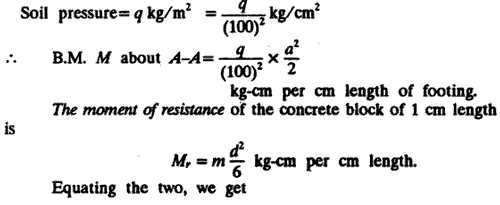
The depth of concrete bed block depends upon the type of concrete, the projection of the block and the soil bearing pressure. It is found on the basis of the bending moment imposed on it, and on the basis of safe modulus of rupture.


For a footing shown in Fig. 3.3 let

d = depth of concrete block in cm.
a = projection beyond the masonry face in cm.
m = safe modulus of rupture of concrete mix, in kg/cm^2.
q = net soil bearing pressure, in kg/m^2.

FIG. 3.3

The projected concrete block will be subjected to bending moment due to upward soil presure q. The maximum B.M. will  be about plane A-A. Consider 1 cm length of the footing ( or wall ).


In the above expression, q and m are in the same units (KN/m^2) while d and a area also in the same units ( i.e. either in mtres or in cm or in mm).

Equation 3.4 (a) is also valid if both q and m are expressed in t/m^2 units.

The value of modulus of rupture m for various types of concrete are given in Table 3.2


TABLE 3.2 SAFE MODULUS OF RUPTURE OF CONCRETE.