Showing posts with label RAFT FOUNDATIONS. Show all posts

Tuesday, January 22, 2013

Design - Jacking Raft

Introduction
Raft foundations suitable for jacking are specifically designed versions of crust rafts, cellular rafts, lidded cellular rafts, beam strip rafts or other foundations whose stiffness and behaviour is designed to resist the jacking forces and moments involved in the process of re-levelling.

The raft is designed to cater for the bending and shear forces likely to be produced during subsidence and relevelling activity. Jacking points are built into the foundation to allow for re-levelling and the type of raft and
number of jacking points depends to a large extent on the proposed use, the size of the structure and the predicted subsidence likely to occur.

The need for a jacking raft tends to be determined by the unpredictability of subsidence and the practicalities for the building user of re-levelling within the life of the building.

As mentioned previously, domestic sites in areas of brine mining are typical of sites where such foundations have been adopted and basically two design conditions need to be considered.

(1) To design for the normal subsidence condition for the site including bending moments and forces as previously discussed for the raft type.
(2) Additional analysis and design to incorporate the structural requirements to resist stresses and distortions during the jacking operations.

Sizing the design
It can be seen that the initial sizing of the foundation for trial design would be to adopt generous sizes for a standard raft of the type being proposed in anticipation of embracing the jacking stresses.

The stresses produced during jacking are dependent on the restrictions and methods of jacking and therefore tend to be one-off designs for set conditions.

Design - Buoyancy Raft.

Introduction
The buoyancy raft works on a similar principle to that of a floating structure where the support for the raft is mainly obtained by displacing the weight of earth or overburden by the volume of a large voided foundation.

The raft  is described previously and is often economically achieved by making use of the voids as a basement structure (see Fig. 13.42).

Buoyancy foundation/basement.
Fig. 13.42 Buoyancy foundation/basement.

It is designed so that sufficient overburden is removed to allow the superstructure load to be applied to the ground with little or no increase in the original stress which existed on the sub-strata prior to excavation and construction. Thus the structure floats like a ship – which displaces water equal to its own weight.

The bottom slab can form the basement of the proposed building, and be combined with the ground slab and retaining walls to act as the raft. It can also be of cellular form (see Fig. 13.43).

Cellular buoyancy foundation.
Fig. 13.43 Cellular buoyancy foundation.

The raft design takes into account any eccentricity of load and aims to keep differential settlements and tilting within acceptable limits (see Fig. 13.44), which shows how eccentric resultant loads can be caused by the basement projections, producing a uniform bearing pressure.


Eccentrically loaded buoyancy raft.
Fig. 13.44 Eccentrically loaded buoyancy raft.
Since buoyancy foundations are expensive compared to more traditional forms they tend only to be used where suitable bearing strata is at too great a depth for other more traditional alternatives. For this reason the foundation tends to be restricted to sites on very deep alluvial deposits such as soft sands and silts and where loads on the foundations can be kept concentric. Examples of such building types would be schemes where deep basements can be economically incorporated into the design or where underground tanks are required.
The cases therefore where the engineer would adopt such solutions tend to be limited.

2 Sizing the design
The overall sizing of the design would generally involve:

(1) Calculating the depth plan size and centre of gravity required for the overburden removal to suit structural buoyancy.
(2) Comparing the results of (1) with the requirements for tanks or basements to suit client’s needs.
(3) Calculating the water pressure for (1) to check for  flotation.
(4) Combining the requirements of (1), (2) and (3) into a mutually suitable voided foundation.
(5) Designing the external walls, floors, roof and separating wall elements for the pressures, bending moments and shear forces including any projections to prevent flotation.

Monday, January 21, 2013

Design - Beam Strip Raft.

Introduction
The beam strip raft is described in section 9.4.7 and consists of downstand beams in two directions tied together by a ground bearing slab. The beam and the slab are designed as separate elements which are combined together to finalize the rafted design.

These rafts are used where the bearing capacity below the beams is relatively good as is the bearing capacity of the ground below the slab and therefore there is no need to design the total raft foundation when the two are linked  in the final drawing.

The two are generally linked because of the added performance from the two separate elements when they are cast monolithic. The beams may be required due to the point loads from column structures around the edge of the raft  or within the body of the raft and beams are designed to span horizontally between these point loads. Similarly the raft slab is designed to float on the ground between the beams but since the bearing capacity where these rafts  are adopted is relatively good then a nominal design incorporating a top and/or bottom mesh is all that is required  in the slab.

These foundations are generally used in areas where quite shallow sand deposits occur below the topsoil and where there is no need to go to excessive depths around the edges of these rafts for heave or other problems. They can also be used where the strata changes slightly from perhaps clayey sands to sandy/silty clays.

Sizing of the design
The sizing of the sections is carried out by treating the beam strips as independent beams, designed previously.

These two parts for the foundation are then tied as shown in Fig. 13.39.

Beam strip raft.
Fig. 13.39 Beam strip raft.


Any necessary adjustments that the engineer may feel are required due to the changes in behaviour resulting from combining the elements are then made in the detailing of the raft. For example, the linking together will generally improve the raft performance by reducing the stresses in the two elements from those applicable if they acted alone.

However, there will be some occasions, for example, when a local heavy load occurs on a downstand, where a local detail could become critical due to the change in behaviour, and additional reinforcement or a slight adjustment to a detail may be needed.

Design - Lidded Cellular Raft.

Introduction
The lidded cellular raft is described previously and due to its formation tends to be a little less stiff than the true  cellular raft. The design calculations however follow similar lines with the exception that the cross-section of the beams tends to be restricted to inverted T and L shapes.

The advantage of this form over the pure cellular raft is that the upper slab can be detailed to allow it to be re-levelled should the floor tilt or distortion become excessive for the building’s use. Also in some locations the top of the lidded raft can be constructed in precast units and may prove  more economic, avoiding the possible need for permanent formwork.

The raft is usually designed as a number of intersecting inverted  T beams taking advantage of the lower ground slab as the flange of the  T but ignoring the upper slab  which could be constructed in timber joists and boards or other form to suit the design requirements (see Fig. 13.37).


Lidded cellular raft.
Fig. 13.37 Lidded cellular raft.

Remember that the strength advantage of the T beam can only be used for midspan, where compression occurs in the bottom of the beam. The section below the column must be designed as rectangular.

The detail at the seating of the upper floor depends upon the need for re-levelling and the possible number of times adjustments may need to be made.

As explained in section 9.4.6, the upper floor of the lidded raft is a separate structure to the main inverted  T and  L beams forming the concrete raft.

Sizing the design
The design procedure is similar to that of the cellular raft except that the upper deck is simply designed to span as  a floor between the up-standing ribs. The remainder of  the design follows the same procedure as before with the exception already mentioned that the element sections become inverted T or L beams rather that I or box sections.

Design - Cellular Raft.

Introduction
Cellular rafts are used where valuable increases in bearing capacity can be achieved by the removal of overburden or where severe bending moments may be induced due to mining activity, seismic loadings, etc.

The cellular form in such situations can perform two functions (see Fig. 13.31).

The foundation while being economic for such situations is one of the most expensive foundation types used.

Cellular raft.
Fig. 13.31 Cellular raft.

Sizing the design
In the case of overburden removal the depth required may relate more to the excavation required to produce adequate reduction in load than to the bending moment resistance of the cellular form (see Fig. 13.32).

Raft depth dictated by bearing requirements.
Fig. 13.32 Raft depth dictated by bearing
requirements.

On the other hand it is more common for the raft depth to relate to the moments likely to be induced and the reduced overburden load to be a resulting bonus. For example, a raft designed to resist seismic loads or mining subsidence may need to be designed to span two-thirds of its total length and to cantilever one-third of its length. Similarly rafts on variable ground subjected to large differential settlements may require such design parameters. This requirement  on a building plan which is restricted to say 20 m on any one side can produce very large shear forces and bending moments thus requiring deep rectangular, I or box sections.

The size of these beams can often be reduced by jointing buildings into smaller units (see Chapter 6). Cellular rafts or other rafts which are formed from beams crossing at right angles are difficult to assess since loads are resisted in two directions by the framework. The designer must start by calculating the design column loads and relating these to the overall plan and ground pressures.

The calculations for the ground pressures based upon the centre of gravity of the loads and the relative stiffness of the raft foundation is then considered. In the case of the cellular raft a stiff raft would normally be assumed (see Fig. 13.33). With reference to Fig. 13.33, the centre of gravity of the load would be calculated in the normal way and the resultant load would be the total addition of the loads on the frame- work for the design conditions being considered.

Centre of gravity of load on stiff raft.
Fig. 13.33 Centre of gravity of load on stiff raft.

The ground pressures at the corners of the raft would then be determined. Assume the resultant total load to be T, the total area to be A, the moment in each of the two directions to be Mx and My, the eccentricity in each direction to be ex and ey, and the section modulus in those directions assum- ing symmetrical plan to be Zx and Zy. The stress at each corner would equal


Mx and My, being the resultant moments, equal T × ex and  T × ey, respectively (see Figs 13.34 and 10.18).

Foundation in biaxial bending.
Fig. 10.18 Foundation in biaxial bending.

As usual in design calculations these theoretical pressures will not necessarily be achieved on site and the difficulty then arises when the engineer tries to assess the actual ground pressures. These pressures will be dependent on the sub- strata, the flexibility of the raft, the actual loads occurring at any time and the time at which these pressures are considered relative to the original application of the load.

None of these conditions can be assessed accurately nor is it necessary to do so. The procedure to be adopted is for the engineer to apply the art of foundation design in producing calculations and details for the raft. This means taking consideration of these variables as part of the refinement of the design at the detailing stage. Adjustments must be made  to sections, reinforcement, location of joints and to the number of beams on plan to produce a more realistic and practical solution. The authors make no apology for suggesting that foundation engineering is an art as well as  a science since they have learnt this art from long and bitter
experience. The engineer doing this exercise therefore would begin by preparing a rough layout from practical experience indicating rough sizes likely to be required.

Assumptions are then made, for example:

(1) The raft will be assumed to be stiff.
(2) The bearing pressure will be assumed to be trapezoidal, as indicated in Fig. 13.34.
(3) The load from the structure will be assumed to be fixed at the design load for the analysis.
(4) The reactions to each beam line will be assumed to be proportional to the bearing area and ground pressure on that line and when both directions are totalled they must be equal to the applied load at that point from the structure.

Corner pressure below stiff raft with resultant load as Fig. 13.3.
Fig. 13.34 Corner pressure below stiff raft with
resultant load as Fig. 13.3.

Many methods of analysing foundations have been proposed, some assuming springs below the foundations, some assuming uniform bearing pressure, some assuming non- linear bearing pressures, some trying to take into account the stiffness of the raft foundation.

At the end of the day the experienced engineer fully under- stands that all these calculated methods, while being  reasonable and theoretically logical, are not realistic. The foundation which the engineer designs will not sit on the soil which was taken to the laboratory for testing, it will  not for its total life be resisting the loads calculated, it willnot be of the stiffness assumed, it will not be subjected to
the settlements or movements anticipated by calculation.

With all this in mind the engineer uses analysis as one of the tools in the kit bag. The above knowledge produced by design and calculation is taken into account and the design adjusted in a direction which is more realistic.

To achieve this practical engineers will often make simple assumptions to produce a quicker analysis while satisfying themselves of the foundation requirements without the need for complicated and often less accurate methods of analysis. A typical design approach for a cellular raft is shown in the following example.

Thursday, January 17, 2013

Design Example: Slip Sandwich Raft.

The nominal crust raft for a pair of semi-detached properties in Design Example 1 is now assumed to be located in a mining area. It will therefore be reworked as a slip sandwich raft, to accommodate the associated ground strains.

The slip sandwich raft is designed on the assumption that the two halves of the raft – on either side of the centreline – are moving away from each other (tension), or towards each other (compression). The maximum horizontal force across the centreline of the raft, arising from the horizontal strains in the underlying ground, is equal to the maximum frictional force which can be transmitted across the slip-plane into one half of the raft.

Vertical loadings
Loads are as Design Example 1 (see Fig. 13.15):

Raft detail – low-rise/lightly loaded buildings.
Fig. 6.15 Raft detail – low-rise/lightly loaded buildings.

Horizontal force across raft centreline
The raft is 10.0 m × 12.0 m. With reference to Fig. 13.30, the total ultimate vertical load on one half of the raft is


located at the level of the underside of the raft thickenings to act as a slip-plane (see Fig. 13.30). The raft will be assumed to behave as illustrated in Fig. 6.14 and Fig. 13.27.


Effect of ground strain on raft.
Fig. 6.14 Effect of ground strain on raft.

The Coal Authority guidelines(4) recommend the use of a coefficient of friction of µ= 0.66 for a sand slip-plane. The length of the centreline is B = 10.0 m. The horizontal force per metre length across the centreline of raft is therefore given by

Reinforcement design for raft tension
Provide high yield reinforcement to resist this force in  tension such that

Provide two layers of A193 mesh throughout, as shown in Fig. 13.30.

Design for raft compression
The same tensile force calculated above can also act in com- pression. By inspection the raft concrete can accommodate this magnitude of compressive stress.

Design - Slip Sandwich Raft.

1. Introduction
This raft is mainly used in active mining areas or where  clay is creeping on inclined sand beds where the horizontal  ground strains set up during subsidence or creep movements would cause damage to the structure, if allowed to be transferred up to it via the foundation (see Fig. 13.23).

Effects on foundations from horizontal ground strains.
Fig. 13.23 Effects on foundations from horizontal
ground strains.

By using a slip-plane of known resistance, the maximum force which can be transferred from the ground to the building before the plane ruptures can be calculated, and the raft designed to resist this force in any direction that it is likely to occur.

The raft can be a flat slab profile thus avoiding the use  of downstand thickenings which may pick up excessive passive load from the ground strain. Alternatively a slab with medium thickenings incorporating a design which provides a slip-plane below the hardcore dumplings (i.e. the raised areas of hardcore protruding up between the beam lines) can be used (see Fig. 13.24).


Alternative slip sandwich rafts.
Fig. 13.24 Alternative slip sandwich rafts.

The ideal ground (i.e. uniform firm layers of non-frost- susceptible low shrinkability sub-strata) to facilitate a flat slab rarely occurs on the site to be developed. Therefore,  to prevent damage from frost, clay heave or differential  settlement, thickenings are often necessary. In such situ- ations the ground strains being picked up either have to  be designed to be resisted by the raft or a slip-plane layer  provided below the level of the downstands to reduce  the forces being transferred. The upper raft (above the  slip plane layer) of a slip sandwich raft can be any of the other rafts already designed and discussed in earlier sections  of this part.

The difference between the slip sandwich raft and the other rafts relates to the slip-plane layer below the slab and the horizontal forces produced from the ground strains transferred through the slip-plane.

The additional stresses are analysed by calculating the forces transferred from the ground strain and these forces are added to the design conditions already discussed for other rafts.

2 Design decisions
The design decision to use a slip sandwich raft will depend totally on the possible existence of critical horizontal ground strains in the sub-strata during the life of the building and the need to restrict these forces to prevent them being trans- ferred in total to the superstructure. The use of jointing to reduce the overall building into small independent robust units is part of the design process. In addition the possible need to incorporate compressible aprons around the raft requires consideration in the design and it is dependent upon the directions and magnitude of the ground strains (see Fig. 13.25).

Section through raft and compressive apron.
Fig. 13.25 Section through raft and compressive apron.

3 Sizing the design
The basic sizing of the raft to sit on the slip-plane would  follow the principles already discussed in other sections of this part.

The additional requirements for the slip sandwich raft however relate to the compressive and tensile forces likely to be transferred through the slip-plane from the ground strains. If a simple rectangular plan shape raft is considered as shown in Fig. 13.26 (which would be the ideal plan shape for such a raft) and a 150 mm thick sand slip-plane, the  following simple analysis can be applied. Assume the total weight of the building and foundations to equal T and the frictional resistance of the sand slip-plane layer to be equal to µ (see Fig. 13.27), the largest horizontal force which can be transferred up from the ground strain through the slip-plane will be equal to (µT)/2. The reason for the total load acting down being halved is that the maximum force that can be transferred as tension through the building must be reacted by the other half of the load. This formula assumes that no other passive forces are being transferred to the foundation, i.e. that all forces are transferred via the sand as a frictional force. In practice the downstand beams would be cast with sloping internal faces as in Fig. 13.30.

Simple rectangular raft.
Fig. 13.26 Simple rectangular raft.


Forces on foundation from ground strains.
Fig. 13.27 Forces on foundation from ground strains.


Slip sandwich raft design example.
Fig. 13.30 Slip sandwich raft design example.

If however downstands project below the raft then the  slip-plane layer should be positioned below such down-stands and the downstands kept to a minimum. In addition if compressive ground strains are occurring then an apron must be introduced to prevent or restrict the amount of strain transferred from passive pressure on the raft edges. If such pressures cannot be avoided then they must be added
to the force indicated above and allowed for in the design.

Any eccentricities of such forces should also be taken into account in the design of the raft since these will produce bending in the raft foundation (see Fig. 13.28) which indicates an eccentric force on a downstand raft thickening.
Passive forces on raft downstands.
Fig. 13.28 Passive forces on raft downstands.

If the plan shape adopted is not rectangular, for example, the L shape as shown in Fig. 13.29, then the two halves of the building producing the force (µT)/2 from frictional resistance below the surface will produce tensile or com- pressive forces across a line which passes through the  centre of gravity of the building and which will tend to rotate towards a line parallel to the subsidence wave.

Consideration must be given therefore to the additional stresses produced by these forces including any bending moments across this face or on lines parallel to the face  (see Fig. 13.29). Division of the slab into two separate  rectangular rafts by the incorporation of a movement joint could be considered as an alternative approach. The significant movements likely to occur here would however have to be allowed for in the detailing of the joint through the structure.

Direction of tensile failure dependent on direction of wave face.
Fig. 13.29 Direction of tensile failure dependent on
direction of wave face.

Monday, January 14, 2013

Crust Raft - Design.

1 Introduction
The crust raft is discussed  previously where it is explained that it is a stiffer and stronger version of the
nominal crust raft. In this chapter it is intended to take this a stage further through the design procedure and to an actual example.

2 Design decisions
The crust raft is used where normal ground bearing substrata is relatively poor, where the depth to good load-bearing soils is excessive, but where by dispersing the  loads differential settlements can be controlled. It is more attractive where these conditions exist on a relatively level site, i.e. where few steps or changes in level exist.

The considerations for thickening layout and profile are as for the nominal crust (see section 13.2).

The design of the crust raft and its element cross-sections tends to be based on a similar simplified analysis to that of the nominal crust raft but adopting a slightly more analytical approach. However, in order to arrive at a suitable span and depression diameter a more detailed analysis of the ground conditions would be carried out. For example, if the raft was to span over possible swallow-holes or shallow
mine workings a detailed study of borehole information particularly with regard to the existence of voids below ground, combined with historical evidence of previous  collapses/depressions would be carried out. Excessively large voids or voids which were creating particular prob- lems in the design of the raft could be considered for grouting in order to reduce the risk of collapse and reduce the diameter of design depressions. If grouting was to be adopted then this would be carried out prior to construction of the raft foundation.

When studying old shallow mine workings reference should be made to Chapter 6. Historical details of pillar and stall workings may be used in the anticipation of the maximum diameter of collapse at cross-over positions, etc. (see Fig. 13.16).

Subsidence prediction for shallow mine working.
Fig. 13.16 Subsidence prediction for shallow
mine working.

A word of caution should be given at this stage with regard to the reliance on mining records since, as was emphasized previouly, while shaft locations are often quite accurate any records of pillar and stall workings tend to be less reliable. This is due to disintegration during oxidation of the pillars, and/or the practice of robbing pillars at the end  of the workings’ normal life. These actions result in a tendency for larger depressions to occur but usually within  a shorter period after completion of the mine workings.

The earlier completion of subsidence is an advantage. In some cases, however, if pit props have remained in position un-rotted, early subsidence is prevented. These sorts of conditions will be taken into account by the experienced engineer in assessing the borehole records and other records of the possible collapse mechanism and type and size of void or depression to be spanned or grouted.

Design Example: Nominal Crust Raft.

A new housing estate, consisting of two-storey semi- detached properties, is to be built on a green field site.
The ground conditions consist of a soft to firm clayey sand.

The net allowable bearing pressure for raft design is estimated at na = 100 kN/m2.

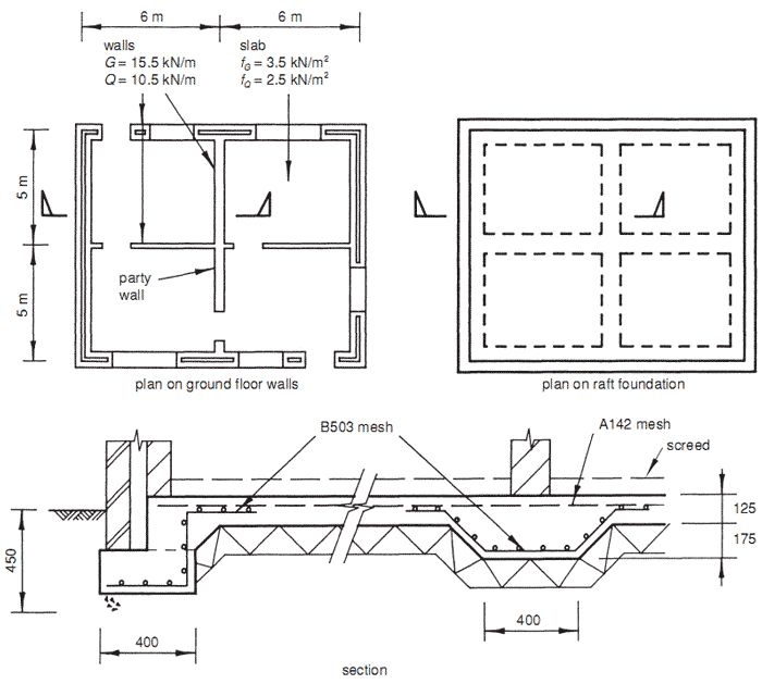
The foundation for each pair of houses is to be designed  as a raft foundation. Taking into account the ground conditions and the relatively light loading, a nominal crust raft  is considered adequate. The wall layout, loadings, and  corresponding raft layout are shown in Fig. 13.15.

Nominal crust raft design example.
Fig. 13.15 Nominal crust raft design example.

Loadings
The foundation load due to slab self-weight and imposed
load is


fQ as a percentage of  f is 100fQ/f = 42%. From Fig. 10.20,  the combined partial safety factor for the foundation load is γF = 1.48.

Wall line load, P = (wall dead load) + (wall imposed load)
     = G + Q
     = 15.5 + 10.5
     = 26.0 kN/m

Q as a percentage of P is 100Q/P = 40%. From Fig. 10.20, the combined partial safety factor for the superstructure loads is γP = 1.48.

Blanket raft construction.
Fig. 13.20 Blanket raft construction.

Bearing pressure design
Because of the low level of loading, no explicit check on bearing capacity is considered necessary.

Design span for local depressions
With reference to Table 13.1, the soil conditions are taken  to be medium Class B. From Fig. 13.5, assuming 150 mm of hardcore, the design span L is 1.6 m.


Design diameter for local depressions
Table 13.1 Design diameter for local depressions

Slab design
It is intended for the slab to have top mesh reinforcement only. Figure 13.5 indicates that, for a design span of 1.6 m,  a minimum average effective depth of 100 mm is required to comply with the deflection requirements of BS 8110:  Part 1(2). A slab thickness of 125 mm will therefore be adopted, with 20 mm top cover. For shrinkage purposes, Table 13.2 indicates, for a 12 m long slab, that A142 mesh is adequate.

 Shrinkage reinforcement for raft slabs
Table 13.2 Shrinkage reinforcement for raft slabs

Because of the low level of distributed load, and the absence of any significant wall line loads on the slab, there is no need to carry out a local spanning check on the slab under ultimate loads. (If however, the internal thickenings were omitted, and the slab required to carry their load, a check should be carried out in a similar manner to Design Example 2 in section 13.3.3.)

Beam thickening design
Similarly, the low level of loading, and the absence of concentrated point loads on the thickenings, indicate that these can be sized and reinforced on a nominal basis.

For external thickenings, use pre-bent B503 mesh, as shown in Fig. 13.15, with the main T8 bars at 100 mm centres  running along the length of the beam. This will result in  at least three T8 longitudinal bars in the top and bottom  of the beam.

For internal thickenings, again use pre-bent B503 mesh,  as shown in Fig. 13.15, with the main bars again running longitudinally to help span over local depressions.

Design - Nominal Crust Raft – Semi-Flexible

1 Design decisions
As discussed previouly the nominal crust raft is used where loadings are relatively light and ground conditions reasonable. The raft is lightly reinforced and consists of a basic ground slab with nominal thickenings (see  Fig. 13.15).

Nominal crust raft design example.
Fig. 13.15 Nominal crust raft design example.

2 Sizing the design
Such rafts can be designed either from experience simply by adopting a known raft which has performed successfully on similar ground conditions and subjected to similar loadings or by calculation as discussed previously.

Many local authorities have ‘standard’ designs which have been approved for use and are often agreed as ‘deemed to satisfy’ building insurers’ requirements. It is wise to agree with building control the design methodology prior to preparation of detailed calculations.

The calculated design assumes that the slab and thickening should be capable of spanning and cantilevering over any local depressions which may occur as a result of the loading and/or sub-strata conditions.

Such rafts are used generally for relatively lightly loaded conditions on reasonable ground. In such conditions these lightly reinforced rafts can prove more economic than strip footings particularly where the ground is reasonably level, where the basic ground slab is used as the main body of  the raft and where small straight thickenings replace  complicated layouts of wall strips.

The layout of the downstands is determined from the  overall raft stiffness requirements and while heavy load lines and point loads will have a bearing on the location  of such downstands they should not be allowed to dictate the design. For example, the strip wall loadings, shown in Fig. 13.10, zig-zags across the building and if the downstand thickenings were made to follow these lines an overall weakness in the thickenings would result at each change in direction and hence the overall behaviour of the raft would be adversely affected.


Zig-zag wall layout.
Fig. 13.10 Zig-zag wall layout.

It is therefore important that a common straight line across the building is used for the downstand which caters for  the local heavy loads and overall stiffness (see Figs 13.11 and 13.12).


Straight thickenings below raft
Fig. 13.11 Straight thickenings below raft.

Irregular wall layout but straight thickenings.
Fig. 13.12 Irregular wall layout but straight
thickenings.

With regard to overall thickening layouts it may be necessary when considering total raft behaviour to introduce thickenings purely for stiffness and in locations where no vertical load lines exist (see Fig. 13.13).

Thickening layout for raft stiffness.
Fig. 13.13 Thickening layout for raft stiffness.

For raft foundations adequate protection from weathering and frost effects on most granular soils, sandy clays and insensitive clays can be achieved with 450 mm cover, similar to road construction. Over-emphasis on clay shrinkage must not be allowed to change the engineering judgement in such soils particularly where past performance has been proven.

The raft is considered as a single element in determining overall behaviour taking account of the stiffness of the  raft, and then breaking the foundation down into a num- ber of small elements to simplify the design. These local conditions tend to dictate the cross-section dimensions of the foundations with the overall behaviour being devel- oped and incorporated into the design on the drawing board. For example, if we take the raft shown in Fig. 13.13 and adopt the internal thickening layout discussed it can be seen that the reinforcement details for overall slab behaviour should ensure that beam thickenings can act continuously. In particular the design should avoid local weakenings in the concrete profile or reinforcement in vulnerable locations such as the internal angles of the raft (see Fig. 13.14). The detail therefore must ensure strong inter-sections at these locations where the overall shape of the raft tends to weaken structural behaviour.

Weak and improved thickening layouts.
Fig. 13.14 Weak and improved thickening layouts.

Bearing Pressure Design - Semi-Fexible Rafts.

Rafts are intended to take local stress concentrations, i.e. line and point loads, and spread them over a larger area by the time they reach the formation level, so as not to exceed the allowable bearing pressure. This is done through the combined influence of concrete thickness and profile, rein- forcement, and thickness of hardcore/granular fill. Where local bending of the raft is utilized to spread the loads over a wider area, an ultimate limit-state analysis is carried out to size the necessary reinforcement.

(1) Slabs
While the slab thickness does contribute to the spread  of concentrated loads, the main factor is the presence or absence of bottom reinforcement. In slabs with top rein- forcement only, the load is assumed to spread through  the slab at 45°, i.e. as if it were mass concrete. In slabs with bottom reinforcement, the reinforcement can act with the slab to form a local spread footing, distributing the load over a wider distance. These cases are shown in Fig. 13.1.

Bearing pressure design for internal walls on slabs without thickenings.
Fig. 13.1 Bearing pressure design for internal walls on
slabs without thickenings.


(2) Internal beam thickenings
The width over which the load is assumed to spread is  primarily governed by the arrangement of reinforcement.

The presence or absence of transverse reinforcement in  the thickenings, and bottom reinforcement in the slabs, determines whether the load can be spread merely over the bottom soffit of the thickening, or additionally over any sloping sides to the thickening or the adjacent slab. These cases are shown in Fig. 13.2. It is recommended that the slab is made thick enough to resist the applied shear, without the use of shear reinforcement.

Bearing pressure design for internal beam thickenings.
Fig. 13.2 Bearing pressure design for internal beam thickenings.

(3) External beam thickenings
With external beam thickenings, the effect of eccentric loads is often the most dominant factor. With reference to Fig. 13.3 (a), the bearing pressure is initially checked assuming a uniform pressure distribution of width 2x located concentrically below the load. If the bearing pressure must be reduced, this is done either by increasing x (the projection of the thickening beyond the line of action of the load) or by spreading the load further into the raft, and using the slab reinforcement to transfer a moment to a suitable reaction to balance the vertical loading eccentricity (see Fig. 13.3 (b) and (c)). This latter approach tends to be the more economic provided:

(a) The opposite edge thickening has a similar load intensity, to balance the moment within the slab, and
(b) The slab reinforcement is sufficient for this moment to develop.

Bearing pressure design for external beam thickenings.
Fig. 13.3 Bearing pressure design for external beam thickenings.


(4) Effect of compacted hardcore/granular fill
The presence of compacted hardcore or granular fill below a raft enables further spreading of concentrated loads, reducing bearing pressures and slab bending moments.

Although almost all rafts have some thickness of hard- core/compacted fill, the beneficial effect of this thickness  is often ignored in practice except where this thickness is substantial. Where the thickness is taken into account a 60° spread is usually assumed (see Fig. 13.4).

 Effect of compacted hardcore fill on bearing pressure design.
Fig. 13.4 Effect of compacted hardcore fill on bearing
pressure design.

Design of Semi-Fexible Raft Layouts

Rafts form a dual  levelling-out function. Firstly they take concentrated loads (stress concentrations) from the superstructure and spread them more evenly onto the ground below; secondly they mitigate the effects of soft spots (local weaknesses) in the supporting ground through local spanning action.

In order for rafts to fulfil this role it is necessary to avoid areas of undue stress concentration and zones of weakness within the raft structure itself. The arrangement and  frequency of raft thickenings – and movement joints  where necessary – to achieve this involve as much art as science. Nevertheless, the following guidelines should be considered when creating a suitable raft layout.

(1) Continuity of thickenings
Thickenings should be continuous wherever possible, with no abrupt terminations or changes in direction. Although a thickening will often be located to coincide with the main load-bearing elements of the superstructure, this is generally not essential. The priority should always be to achieve a consistent and robust arrangement of thickenings. It is recommended that there be sufficient thickenings in both directions to limit the aspect ratio for slab bays (i.e. length : width) to a maximum of 2 : 1.

(2) Avoidance of areas of weakness
Areas of weakness generally occur at re-entrant corners (see Fig. 13.13) and where re-entrant corners occur on both sides, resulting in a significant reduction in width of the slab. Re-entrant corners should be dealt with by ensuring that both of the external thickenings meeting at the corner are continued past the corner as internal thickenings on the same lines. Such areas of weakness within the raft should  be suitably strengthened, with additional thickenings if  necessary; alternatively, the weakness can be ‘acknow-ledged’ by positioning a movement joint at this location (see below and Fig. 13.17).


Thickening layout for raft stiffness.
Fig. 13.13 Thickening layout for raft stiffness.

Crust raft design example – plan layout and loadings.
Fig. 13.17 Crust raft design example – plan layout and loadings.

The other main possible source of weakness in a slab is via poor detailing at thickening junctions and intersections.

Suitable tying reinforcement should be provided at all  corner, tee, and  cross junctions, to ensure thickenings can interact and share load with each other as necessary.

(3) Appropriate use of movement joints 
Movement joints are used to break up a large raft into  a number of smaller rafts. This may be done to reduce  bending moments and shrinkage stresses in a large raft/superstructure, or to avoid areas of stress concentration.

Stress concentrations can occur at local reductions in width within a slab, or at junctions of  limbs with the main mass  of the raft. It is  usually easier to deal with the strain energy associated  with these stress concentrations by introducing a movement joint and allowing movement to occur, rather than strengthening the area by introducing additional reinforcement and thickenings.

It is good practice to avoid excessively large or excessively elongated rafts, and thus a larger building may well need  to incorporate a number of movement joints. It is recommended that rafts be limited to an aspect ratio (length : width) of approximately 4 : 1, and in general a maximum length of 20 m.

It is important that, when a movement joint is introduced into a raft structure, thickenings occur on both sides of the movement joint, to ensure the two halves do both act as independent rafts. The movement joint should be carried up through the superstructure walls and suspended floors; however it is generally not necessary to continue it through a tiled or slated timber roof structure, unless large differential foundation settlements or longitudinal strains are expected.

Design Principles - Semi-Flexible Rafts.

The design approach is based upon the practical assumption that all soils are variable, and all ground improvement treatments are imperfect. While ‘beam on elastic foundation’ and similar analyses have their place, they tend to assume a consistent and uniform formation which does not often accord with reality. Local depressions or soft spots will usually occur, and should therefore, particularly in the case of semi-flexible rafts, be designed for.

This approach to raft design consists of five main steps:

(1) Adopt a sensible layout of beam thickenings to avoid stress concentrations and areas of weakness.
(2) Check bearing pressure under concentrated loads on slabs and beam thickenings.
(3) Establish a design span for local depressions, based  on the ground conditions and thickness of compacted hardcore filling.
(4) Design the raft slab areas to span over local depressions and to resist shrinkage cracking.
(5) Design the raft beam thickenings to span over local depressions.

It should be emphasized that, as with all other aspects of foundation design, it is not possible to exhaustively cover every imaginable situation, i.e. in this case every possible combination of loading, raft profile and reinforcement, compacted fill, and ground conditions. Therefore, although the guidance which follows should cover most normal situations, any new design situation should be looked at wearing one’s ‘engineering spectacles’ to spot those situations where rules need adapting, or do not apply.

Wednesday, December 12, 2012

Raft Foundations - Typical Examples.

When strips become so wide (because of heavy column loads or weak ground) that the clear distance between them is about the same as the width of the strips (or when the depth to suitable bearing capacity strata for strip footing loading becomes too deep), it is worth considering raft foundations. They are useful in restricting the differential settlement on variable ground, and to distribute variations of superstructure loading from area to area. Rafts can be stiffened (as strips can) by the inclusion of tee beams.

Rafts can also be made buoyant by the excavation (displacement) of a depth of soil, similar to the way that seagoing rafts are made to float by displacing an equal weight of water. A cubic metre of soil can weigh as much as three floor loads per square metre, so a deep basement excavation can displace the same weight of soil as the weight of the proposed structure. However where there is a high water-table then flotation of the raft can occur, if the water pressures exceed the self-weight! Typical examples of rafts are shown in Fig. 1.7.


Fig. 1.7 Raft Foundations - Typical Examples.