Showing posts with label DRILLED PIER FOUNDATIONS. Show all posts

Friday, December 7, 2012

BJERRUM AND EIDE (1956) METHOD OF ANALYSIS.

The method of analysis discussed earlier gives reliable results provided the width of the braced cut is larger than the depth of the excavation and that the braced cut is very long. In the cases where the braced cuts are rectangular, square or circular in plan or the depth of excavation exceeds the width of the cut, the following analysis should be used.

In this analysis the braced cut is visualized as a deep footing whose depth and horizontal dimensions are identical to those at the bottom of the braced cut. This deep footing would fail in an identical manner to the bottom braced cut failed by heave. The theory of Skempton for computing Nc (bearing capacity factor) for different shapes of footing is made use of. Figure 20.32 gives values of Nc as a function of H/B for long, circular or square footings. For rectangular footings, the value of Nc may be computed by the expression


Figure 20.32 Stability of bottom excavation (after Bjerrum and Eide, 1956)

Tuesday, December 4, 2012

CASE STUDY OF A DRILLED PIER SUBJECTED TO LATERAL LOADS.

Lateral load test was performed on a circular drilled pier by Davisson and Salley (1969). Steel casing pipe was provided for the concrete pier. The details of the pier and the soil properties are given in Fig. 17.28.

The pier was instrumented and subjected to cyclic lateral loads. The load deflection curve as obtained by Davison et al., is shown in the same figure.

Direct method (Murthy and Subba Rao, 1995) has been used here to predict the load displacement relationship for a continuous load increase by making use of Eq. (16.29). The predicted curve is also shown in Fig. 17.28. There is an excellent agreement between the predicted and the observed values.


Figure 17.28 Load deflection relationship, Pier 25 (Davisson et al., 1969)

UPLIFT CAPACITY OF DRILLED PIERS.

Structures subjected to large overturning moments can produce uplift loads on drilled piers if they are used for the foundation. The design equation for uplift is similar to that of compression. Figure 17.22 shows the forces acting on the pier under uplift-load Qul. The equation for Qul may be expressed as


Uplift Capacity of Single Pier (straight edge)
For a drilled pier in cohesive soil, the frictional resistance may expressed as (Chen and Kulhawy, 1994)


Poulos and Davis, (1980) suggest relationships between cu and α as given in Fig. 17.23. The curves in the figure are based on pull out test data collected by Sowa (1970).

Uplift Resistance of Piers in Sand
There are no confirmatory methods available for evaluating uplift capacity of piers embedded in cohesionless soils. Poulos and Davis, (1980) suggest that the skin frictional resistance for pull out may be taken as equal to two-thirds of the shaft resistance for downward loading.

Uplift Resistance of Piers in Rock
According to Carter and Kulhawy (1988), the frictional resistance offered by the surface of the pier under uplift loading is almost equal to that for downward loading if the drilled pier is rigid relative to the rock. The effective rigidity is defined as (Ec/Em)/((d/Ds)^2), in which Ec  and Em  are the Young's modulus of the drilled pier and rock mass respectively, d is the socket diameter and DS is the depth of the socket. A socket is rigid when (Ec/Em)/((d/Ds)^2)  > 4. When the effective rigidity is less than 4, the frictional resistance fr for upward loading may be taken as equal to 0.7 times the value for downward loading.
Figure 17.22 Uplift forces for a straight edged pier

ESTIMATION OF SETTLEMENTS OF DRILLED PIERS AT WORKING LOADS.

O'Neill and Reese (1999) suggest the following methods for computing axial settlements for isolated drilled piers:

1. Simple formulas
2. Normalized load-transfer methods

The total settlement St  at the pier head at working loads may be expressed as (Vesic, 1977)


The equations for the settlements are


Table 17.7 Values of Cp for various soils (Vesic, 1977)


Normalized Load-Transfer Methods
Reese and O'Neill (1988) analyzed a series of compression loading test data obtained from full-sized drilled piers in soil. They developed normalized relations for piers in cohesive and cohesionless soils. Figures 17.18 and 17.19 can be used to predict settlements of piers in cohesive soils and Figs. 17.20 and 17.21 in cohesionless soils including soil mixed with gravel.

The boundary limits indicated for gravel in Fig. 17.20 have been found to be approximately appropriate for cemented fine-grained desert IGM's (Walsh et al., 1995). The range of validity of the normalized curves are as follows:

 Figure 17.18 Normalized side load transfer for drilled shaft in cohesive soil (O'Neill and Reese, 1999)


Figure 17.19 Normalized base load transfer for drilled shaft in cohesive soil (O'Neill and Reese, 1999)


Figure 17.20 Normalized side load transfer for drilled shaft in cohesionless soil (O'Neill and Reese, 1999)


Figure 17.21 Normalized base load transfer for drilled shaft in cohesionless soil (O'Neill and Reese, 1999)

 
Figures 17.18 and 17.19
Normalizing factor = shaft diameter d
Range of d = 0.46 m to 1.53 m
 
Figures 17.20 and 17.21
Normalizing factor = base diameter
Range of d = 0.46m to 1.53m

The following notations are used in the figures:

Monday, December 3, 2012

VERTICAL BEARING CAPACITY OF DRILLED PIERS - DRILLED PIER FOUNDATIONS.

For the purpose of estimating the ultimate bearing capacity, the subsoil is divided into layers (Fig. 17.12) based on judgment and experience (O'Neill and Reese, 1999). Each layer is assigned one of four classifications.

1. Cohesive soil [clays and plastic silts with undrained shear strength cu <= 250 kN/m2 (2.5 t/ft^2)] .

2. Granular soil [cohesionless geomaterial, such as sand, gravel or nonplastic silt with uncorrected SPT(N) values of 50 blows per 0.3/m or less].

3. Intermediate geometerial [cohesive geometerial with undrained shear strength cu between 250 and 2500 kN/m^2 (2.5 and 25 tsf), or cohesionless geomaterial with SPT(N) values > 50 blows per 0.3 mj .

4. Rock [highly cemented geomaterial with unconfmed compressive strength greater than 5000 kN/m^2 (50 tsf)].

The unit side resistance fs (=fmax) is computed in each layer through which the drilled shaft passes, and the unit base resistance qb (=qmax) is computed for the layer on or in which the base of the drilled shaft is founded.

The soil along the whole length of the shaft is divided into four layers as shown in Fig. 17.12.

Effective Length for Computing Side Resistance in Cohesive Soil 
O'Neill and Reese (1999) suggest that the following effective length of pier is to be considered for computing side resistance in cohesive soil.

Straight shaft: One diameter from the bottom and 1.5 m (5 feet) from the top are to be excluded
from the embedded length of pile for computing side resistance as shown in Fig. 17.13(a).

Belled shaft: The height of the bell plus the diameter of the shaft from the bottom and 1.5 m (5 ft)
from the top are to be excluded as shown in Fig 17.13(b).


Figure 17.12 Idealized geomaterial layering for computation of compression load
and resistance (O'Neill and Reese, 1999)
 
 
Figure 17.13 Exclusion zones for estimating side resistance for drilled shafts in
cohesive soils

LOAD TRANSFER MECHANISM - DRILLED PIER FOUNDATIONS.

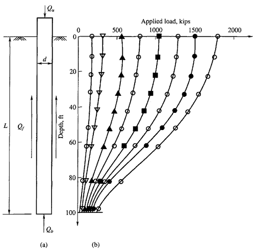
Figure 17.10(a) shows a single drilled pier of diameter d, and length L constructed in a homogeneous mass of soil of known physical properties. If this pier is loaded to failure under an ultimate load Qu, a part of this load is transmitted to the soil along the length of the pier and the balance is transmitted to the pier base. The load transmitted to the soil along the pier is called the ultimate friction load or skin load, Qf and that transmitted to the base is the ultimate base or point load Qb. The total ultimate load, Qu, is expressed as (neglecting the weight of the pier)


If the pier is instrumented, the load distribution along the pier can be determined at different stages of loading.

Typical load distribution curves plotted along a pier are shown in Fig 17.10(b) (O'Neill and Reese, 1999).

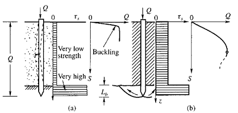
These load distribution curves are similar to the one shown in Fig. 15.5(b). Since the load transfer mechanism for a pier is the same as that for a pile, no further discussion on this is necessary here. However, it is necessary to study in this context the effect of settlement on the mobilization of side shear and base resistance of a pier. As may be seen from Fig. 17.11, the maximum values of base and side resistance are not mobilized at the same value of displacement. In some soils, and especially in some brittle rocks, the side shear may develop fully at a small value of displacement and then decrease with further displacement while the base resistance is still being mobilized (O'Neill and Reese, 1999). If the value of the side resistance at point A is added to the value of the base resistance at point B, the total resistance shown at level D is overpredicted. On the other hand, if the designer wants to take advantage primarily of the base resistance, the side resistance at point C should be added to the base resistance at point B to evaluate Qu. Otherwise, the designer may wish to design for the side resistance at point A and disregard the base resistance entirely.

Figure 17.10 Typical set of load distribution curves (O'Neill and Reese, 1999)


Figure 17.11 Condition in which (Qb  + Qf) is not equal to actual ultimate resistance


Figure 15.5 (b) general shear failure in the strong lower soil

DESIGN CONSIDERATIONS - DRILLED PIER FOUNDATIONS.

The precess of the design of a drilled pier generally involves the following:

1. The objectives of selecting drilled pier foundations for the project.
2. Analysis of loads coming on each pier foundation element.
3. A detailed soil investigation and determining the soil parameters for the design.
4. Preparation of plans and specifications which include the methods of design, tolerable settlement, methods of construction of piers, etc.
5. The method of execution of the project.

In general the design of a drilled pier may be studied under the following headings.

1. Allowable loads on the piers based on ultimate bearing capacity theories.
2. Allowable loads based on vertical movement of the piers.
3. Allowable loads based on lateral bearing capacity of the piers.

In addition to the above, the uplift capacity of piers with or without underreams has to be evaluated.

The following types of strata are considered.

1. Piers embedded in homogeneous soils, sand or clay.
2. Piers in a layered system of soil.
3. Piers socketed in rocks.

It is better that the designer select shaft diameters that are multiples of 150 mm (6 in) since these are the commonly available drilling tool diameters.

Slurry Method of Construction - Drilled Pier Foundations.

The slurry method of construction involves the use of a prepared slurry to keep the bore hole stable for the entire depth of excavation. The soil conditions for which the slurry displacement method is applicable could be any of the conditions described for the casing method. The slurry method is a viable option at any site where there is a caving soil, and it could be the only feasible option in a permeable, water bearing soil if it is impossible to set a casing into a stratum of soil or rock with low permeability. The various steps in the construction process are shown in Fig. 17.9. It is essential in this method that a sufficient slurry head be available so that the inside pressure is greater than that from the GWT or from the tendency of the soil to cave.

Bentonite is most commonly used with water to produce the slurry. Polymer slurry is also employed. Some experimentation may be required to obtain an optimum percentage for a site, but amounts in the range of 4 to 6 percent by weight of admixture are usually adequate.

The bentonite should be well mixed with water so that the mixture is not lumpy. The slurry should be capable of forming a filter cake on the side of the bore hole. The bore hole is generally not underreamed for a bell since this procedure leaves unconsolidated cuttings on the base and creates a possibility of trapping slurry between the concrete base and the bell roof.

If reinforcing steel is to be used, the rebar cage is placed in the slurry as shown in Fig 17.9(b).

After the rebar cage has been placed, concrete is placed with a tremie either by gravity feed or by pumping. If a gravity feed is used, the bottom end of the tremie pipe should be closed with a closure plate until the base of the tremie reaches the bottom of the bore hole, in order to prevent contamination of the concrete by the slurry. Filling of the tremie with concrete, followed by subsequent slight lifting of the tremie, will then open the plate, and concreting proceeds. Care must be taken that the bottom of the tremie is buried in concrete at least for a depth of 1.5 m (5 ft). The sequence of operations is shown in Fig 17.9(a) to (d).

Figure 17.9 Slurry method of construction (a) drilling to full depth with slurry;
(b) placing rebar cage; (c) placing concrete; (d) completed shaft (O'Neill and
Reese, 1999)

Casing Method of Construction - Drilled Pier Foundations.

The casing method is applicable to sites where the soil conditions are such that caving or excessive soil or rock deformation can occur when a hole is drilled. This can happen when the boring is made in dry soils or rocks which are stable when they are cut but will slough soon afterwards. In such a case, the bore hole is drilled, and a steel pipe casing is quickly set to prevent sloughing. Casing is also required if drilling is required in clean sand below the water table underlain by a layer of impermeable stones into which the drilled shaft will penetrate. The casing is removed soon after the concrete is deposited. In some cases, the casing may have to be left in place permanently. It may be noted here that until the casing is inserted, a slurry is used to maintain the stability of the hole. After the casing is seated, the slurry is bailed out and the shaft extended to the required depth.

Figures 17.7(a) to (h) give the sequence of operations. Withdrawl of the casing, if not done carefully, may lead to voids or soil inclusions in the concrete, as illustrated in Fig. 17.8.

Figure 17.7 Casing method of construction: (a) initiating drilling, (b) drilling
slurry; (c) introducing casing, (d) casing is sealed and slurry is being removed
interior of casing (continued)


Figure 17.7 (continued) casing method of construction: (e) drilling below casing
(f) underreaming, (g) removing casing, and (h) completed shaft (O'Neill and
Reese, 1999)


Figure 17.8 Potential problems leading to inadequate shaft concrete due to
removal of temporary casing without care (D'Appolonia, et al., 1 975)

Dry Method of Construction - Drilled Pier Foundations.

The dry method is applicable to soil and rock that are above the water table and that will not cave or slump when the hole is drilled to its full depth. The soil that meets this requirement is a homogeneous, stiff clay. The first step in making the hole is to position the equipment at the desired location and to select the appropriate drilling tools. Fig. 17.6(a) gives the initial location. The drilling is next carried out to its fill depth with the spoil from the hole removed simultaneously.

After drilling is complete, the bottom of the hole is underreamed if required. Fig. 17.6(b) and (c) show the next steps of concreting and placing the rebar cage. Fig 17.6(d) shows the hole completely filled with concrete.

Figure 17.6 Dry method of construction: (a) initiating drilling, (b) starting concrete
pour, (c) placing rebar cage, and (d) completed shaft (O'Neill and Reese, 1999)

METHODS OF CONSTRUCTION: DRILLED PIER FOUNDATIONS.

Earlier Methods
The use of drilled piers for foundations started in the United States during the early part of the twentieth century. The two most common procedures were the Chicago and Gow methods shown in Fig. 17.2. In the Chicago method a circular pit was excavated to a convenient depth and a cylindrical shell of vertical boards or staves was placed by making use of an inside compression ring. Excavation then continued to the next board length and a second tier of staves was set and the procedure continued. The tiers could be set at a constant diameter or stepped in about 50 mm. The Gow method, which used a series of telescopic metal shells, is about the same as the current method of using casing except for the telescoping sections reducing the diameter on successive tiers.

Modern Methods of Construction
Equipment

There has been a phenomenal growth in the manufacture and use of heavy duty drilling equipment in the United States since the end of World War II. The greatest impetus to this development occurred in two states, Texas and California (Woodward et al., 1972). Improvements in the machines were made responding to the needs of contractors. Commercially produced drilling rigs of sufficient size and capacity to drill pier holes come in a wide variety of mountings and driving arrangements. Mountings are usually truck crane, tractor or skid. Fig. 17.3 shows a tractor mounted rig. Drilling machine ratings as presented in manufacturer's catalogs and technical data sheets are usually expressed as maximum hole diameter, maximum depth, and maximum torque at some particular rpm.

Many drilled pier shafts through soil or soft rock are drilled with the open-helix auger. The tool may be equipped with a knife blade cutting edge for use in most homogeneous soil or with hard-surfaced teeth for cutting stiff or hard soils, stony soils, or soft to moderately hard rock. These augers are available in diameters up to 3 m or more. Fig. 17.4 shows commercially available models.

Underreaming tools (or buckets) are available in a variety of designs. Figure 17.5 shows a typical 30° underreamer with blade cutter for soils that can be cut readily. Most such underreaming tools are limited in size to a diameter three times the diameter of the shaft.

When rock becomes too hard to be removed with auger-type tools, it is often necessary to resort to the use of a core barrel. This tool is a simple cylindrical barrel, set with tungsten carbide teeth at the bottom edge.

For hard rock which cannot be cut readily with the core barrel set with hard metal teeth, a calyx or shot barrel can be used to cut a core of rock.

General Construction Methods of Drilled Pier Foundations
The rotary drilling method is the most common method of pier construction in the United States.

The methods of drilled pier construction can be classified in three categories as

1. The dry method   The dry method is applicable to soil and rock that are above the water table and that will not cave or slump when the hole is drilled to its full depth. The soil that meets this requirement is a homogeneous, stiff clay. The first step in making the hole...(more)

2. The casing method   The casing method is applicable to sites where the soil conditions are such that caving or excessive soil or rock deformation can occur when a hole is drilled. This can happen when the boring is made in dry soils or rocks which are stable...(more)

3. The slurry method   The slurry method of construction involves the use of a prepared slurry to keep the bore hole stable for the entire depth of excavation. The soil conditions for which the slurry displacement method is applicable could be any of the...(more)

Figure 17.2 Early methods of caisson construction


Figure 17.3 Tractor mounted hydraulic drilling rig (Courtesy: Kelly Tractor Co,USA)

Figure 17.4 (a) Single-flight auger bit with cutting blade for soils, (b) single-flight
auger bit with hard-metal cutting teeth for hard soils, hardpan, and rock, and (c) cast
steel heavy-duty auger bit for hardpan and rock (Source: Woodward et al., 1972)


Figure 17.5 A 30° underreamer with blade cutters for soils that can be cut readily
(Source: Woodward et al., 1972)

Thursday, November 29, 2012

ADVANTAGES AND DISADVANTAGES OF DRILLED PIER FOUNDATIONS.

Advantages
1. Pier of any length and size can be constructed at the site
2. Construction equipment is normally mobile and construction can proceed rapidly
3. Inspection of drilled holes is possible because of the larger diameter of the shafts
4. Very large loads can be carried by a single drilled pier foundation thus eliminating the necessity of a pile cap
5. The drilled pier is applicable to a wide variety of soil conditions
6. Changes can be made in the design criteria during the progress of a job
7. Ground vibration that is normally associated with driven piles is absent in drilled pier construction
8. Bearing capacity can be increased by underreaming the bottom (in non-caving materials)
 
Disadvantages
1.
Installation of drilled piers needs a careful supervision and quality control of all the materials used in the construction
2. The method is cumbersome. It needs sufficient storage space for all the materials used in the construction
3. The advantage of increased bearing capacity due to compaction in granular soil that could be obtained in driven piles is not there in drilled pier construction
4. Construction of drilled piers at places where there is a heavy current of ground water flow due to artesian pressure is very difficult

DRILLED PIER FOUNDATIONS.

Drilled pier foundations, the subject matter of this chapter, belong to the same category as pile foundations. Because piers and piles serve the same purpose, no sharp deviations can be made between the two. The distinctions are based on the method of installation. A pile is installed by driving, a pier by excavating. Thus, a foundation unit installed in a drill-hole may also be called a bored cast-in-situ concrete pile. Here, distinction is made between a small diameter pile and a large diameter pile. A pile, cast-in-situ, with a diameter less than 0.75 m (or 2.5 ft) is sometimes called a small diameter pile. A pile greater than this size is called a large diameter bored-cast-in-situ pile.

The latter definition is used in most non-American countries whereas in the USA, such large- diameter bored piles are called drilled piers, drilled shafts, and sometimes drilled caissons.