Showing posts with label SLABS. Show all posts

Friday, January 11, 2013

Design Example: Floating Slab.

A ground floor slab is to be designed for a single-storey supermarket measuring 60 m × 36 m on plan, as shown in Fig. 11.49. The slab is required to carry an imposed load of 25 kN/m2. The superstructure is a two bay portal frame on separate foundations, and the soil is a medium dense sand, which the site investigation has indicated to be consistent across the site.

Based on the relatively good ground conditions, a 150 mm concrete slab on 150 mm of hardcore will initially be assumed.
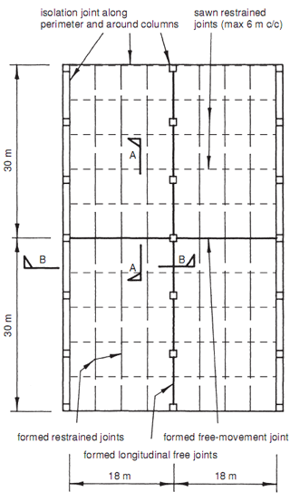
Floating slab design example – plan showing movement joints.
Fig. 11.49 Floating slab design example – plan
showing movement joints.

Joints and reinforcement for shrinkage purposes
The slab is intended to be constructed using the long strip method. The slab will be cast in 60 m × 4.5 m strips, in an alternate bay sequence, as shown in Fig. 11.49. The strips being sawn into 6 m square panels as shown is practicable when the concrete is strong enough to avoid damage to arrises and no later than 24 h after placing. If an A393 mesh is to be used, one formed free-movement joint along the  60 m length of the building will be appropriate.

Similarly, a formed free-movement joint should be provided in the longitudinal direction. The various reinforcement and joint details are shown in Fig. 11.50. Spanning over local depression

Floating slab design example – movement joint details.
Fig. 11.50 Floating slab design example – movement joint details.

(1) Select a diameter for a local depression from Table 11.4.
Modify it if required to take into account the thickness of any compacted granular material/hardcore below
the slab, as per Fig. 13.4 (a).

In this example, with the sub-grade comprising a consistent medium dense sand, a design span of  0.95 m will be used.

(2) Calculate the loads acting over a depression located at an unsupported slab corner, as per Fig. 11.51. (This is the worst case location for a depression.)


Floating slab design example – designing for local depression.
Fig. 11.51 Floating slab design example – designing for local depression.

In this example, the ultimate foundation loads due to slab self-weight and imposed load of 25 kN/m2 is given by
No significant point loads are assumed to act in this particular example.

(3) Calculate the cantilever moment per metre width adjacent to this depression from Fig. 11.51.
An A mesh is proposed, giving a two-way moment of


(4) Calculate the corresponding area of mesh reinforcement required.

An A142 mesh will therefore be satisfactory.
 

Normally this reinforcement, calculated for the worst case condition at a slab corner, would be provided throughout the slab. In situations where this results in an excessive amount of reinforcement, a separate calculation can be  carried out for a depression located in the middle of the slab.

Sizing of the Slab.

In general floor slabs are designed by eye from experience and are made up of a sub-base layer of hardcore blinded with either sand or concrete and sealed with a slip membrane upon which the slab is cast. However, an alternative approach is to consider the make-up and performance requirements in more detail.

Floor slabs supported directly on the ground are subject to bending and shear forces resulting from differential movements in the ground support during loading. In addition they are subjected to thermal and moisture movements which can produce the critical stresses particularly in slabs on uniform support.

Typical reinforcement proportions of 0.1–0.25% will not significantly affect the crack width and distribution. Limiting crack width to say 0.3 mm would require significant amounts of reinforcement of the order of 0.4%. Current thinking is to saw the slab into panels approximately  6 m square, the thermal contraction and drying shrinkage cracks being induced by the saw cuts. The use of square mesh ‘A’-type fabrics is now more common than ‘B’-type fabrics and the ‘small panel’ approach is considered to result in lower risk of cracking than the use of heavy fabric and more widely spaced joints.

The design process therefore should be to calculate the rein- forcement required for ground support, and then decide on sawn or formed joint locations to minimise the thermal and shrinkage stresses in the panels. The analysis for ground support can be assessed by the adoption of a design based upon spanning or cantilevering over a depression similar to that adopted for crust rafts. Due to the relatively small loads applied to slabs, the likely settlement depressions tend to be of small diameter when compared with a similar crust raft condition (see Table 11.3).

Table 11.3 Ground floor slabs – typical assumed depressions
Ground floor slabs – typical assumed depressions

Design Decisions - Floating Slabs.

The design decisions relate to

(1) The loading anticipated on the slab.
(2) The ground conditions below the slab.
(3) The need to maintain specific levels and finishes for a normal design life within appropriate tolerances.
(4) The required durability.
(5) The control of shrinkage and other movements without excessive cracking.

The floating slab is chosen when the sub-strata or a hardcore layer over the sub-strata is suitable to allow a simple slab to adequately disperse the loads without excessive distortions or cracking. Where such conditions do not exist then a suspended slab may need to be adopted.

A floating slab can be of plain concrete or reinforced concrete depending on the quality of the sub-strata and the loading condition. Generally they are reinforced and while it can be argued that under their loading conditions positive and negative bending moments will be produced, it is common to only reinforce with one layer of reinforcement, usually using a mesh fabric. If one layer of reinforcement  is used it can be located in the bottom, top or middle of  the slab, depending on the designer’s requirements. However, generally a top mesh is usually considered the most suitable.

Cracking of concrete slabs is almost inevitable in some form either as a result of shrinkage or bending tensile stress.

Control over such cracking is usually more important on the top surface of the ground floor slab rather than on the underside and by providing the mesh in the top of the slab and accepting some cracking on the soffit the designer can economically control the condition for most ground slabs (see Fig. 11.46).
If, however, there is a need for the slab soffit to be protected then a bottom mesh can also be provided (see Fig. 11.47).


Typical bending and reinforcement in ground bearing slabs.
Fig. 11.46 Typical bending and reinforcement in
ground bearing slabs.


Doubly reinforced ground slab.
Fig. 11.47 Doubly reinforced ground slab.

In all cases one of the most important aspects of the design and construction is to maintain adequate cover for both wear and tear of the surface and to provide adequate durability.

The slab is generally sized and reinforced on the basis of experience. However, as with the crust raft, a calculated design can be adopted using nominal rules based upon the ground condition. For example, assumptions for variations in sub-strata and/or hardcore support can be made on the basis of expected diameter of any soft spot which may have to be spanned or cantilevered (see Fig. 11.48).


Typical design depression.
Fig. 11.48 Typical design depression.

Floating Slabs (Ground Slabs).

Introduction
A floating slab or ground slab can be thought of as the  most common form of raft foundation. It is basically a
concrete slab with limited stiffness and reinforcement suitable to disperse the normal floor loads over a greater area  of sub-strata and to span over any depressions or soft spots.

1 Design decisions   The design decisions relate to (1) The loading anticipated on the slab.(2) The ground conditions below the slab.(3) The need to maintain specific levels and finishes for a normal...

2 Sizing of the slab   In general floor slabs are designed by eye from experience and are made up of a sub-base layer of hardcore blinded with either sand or concrete and sealed with a slip membrane...

3 Design Example: Floating slab  A ground floor slab is to be designed for a single-storey supermarket measuring 60 m × 36 m on plan, as shown in Fig. 11.49. The slab is required to carry an imposed load of 25...