Wednesday, January 29, 2014

STRUCTURES: FORCE VS. STRESS

Force and stress refer to the same phenomena, but with different meanings.  Force is an external action, measured in absolute units: # (pound), k (kip); or SI units: N (Newton),  kN (kilo Newton).  Stress is an internal reaction in relative units (force/area ), measured in psi (pound per square inch), ksi (kip per square  inch); or SI units: Pa (Pascal), kPa (kilo Pascal).  Axial stress is computed as:

f = P / A

where

 f = stress
 P = force
 A = cross section area

Note: stress can be compared to allowable stress of a given material.

Force is the load or action on a member
•  Stress can be compared to allowable stress for any material, expressed as:
 F ≥ f  (Allowable stress must be equal or greater than actual stress)

where

  F = allowable stress
  f = actual stress

The type of stress is usually defined by subscript:

 Fa, fa   (axial stress, capital F = allowable stress)
 Fb, fb   (bending stress, capital F = allowable stress)
 Fv, fv   (shear stress, capital F = allowable stress)

The following examples of axial stress demonstrate force and stress relations:


Note:  The heel would sink into the wood, yield it and mark an indentation

STRUCTURES: FORCE VS. STRESS

Wednesday, January 22, 2014

STRUCTURES - FORCE TYPES

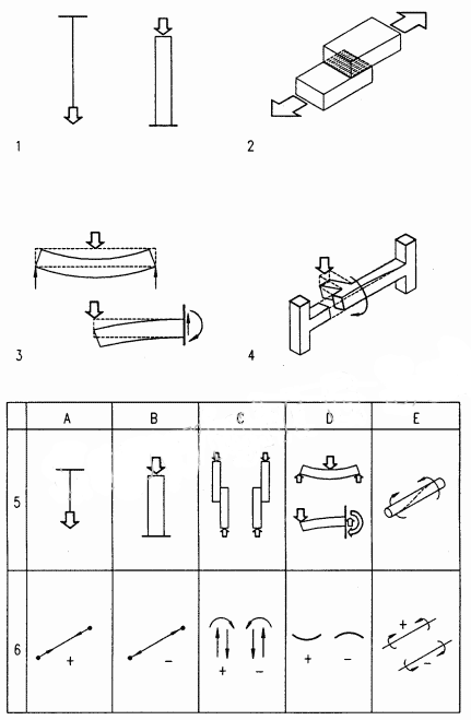
Forces on structures include tension, compression, shear, bending, and torsion.  Their  effects and notations are tabulated below and all but bending and related shear are  described on the following pages.  Bending and related shear are more complex and further described in the next part.


1  Axial force (tension and compression)
2 Shear
3 Bending
4 Torsion
5 Force actions
6  Symbols and notations

A Tension
B Compression
C Shear
D Bending
E Torsion

STRUCTURES - FORCE TYPES

Monday, January 13, 2014

STRUCTURES - SUSPENSION ROOF

Assume:


1  Cable roof structure

2  Parabolic cable by graphic method

 Process:
  Draw AB and AC (tangents of cable at supports)
  Divide tangents AB and AC into equal segments
  Lines connecting AB to AC define parabolic cable envelop

3 Cable profile

 Process:
  Define desired cable sag f (usually f = L/10)
  Define point A at 2f below midpoint of line BC
  AB and AC are tangents of parabolic cable at supports
  Compute total load W = w L

4  Equilibrium vector polygon at supports (force scale: 1” = 50 k)
 Process:
  Draw vertical vector (total load W)
  Draw equilibrium polygon W-Tl-Tr
  Draw equilibrium polygons at left support Tl-H-Rl
  Draw equilibrium polygons at right support Tr-Rr-H
  Measure vectors H, Rl, Rr at force scale

Note:  This powerful method finds five unknowns: H, RI, Rr. Tl. Tr The maximum cable force is at the highest support


Sunday, January 5, 2014

DESIGN FUNICULAR STRUCTURES

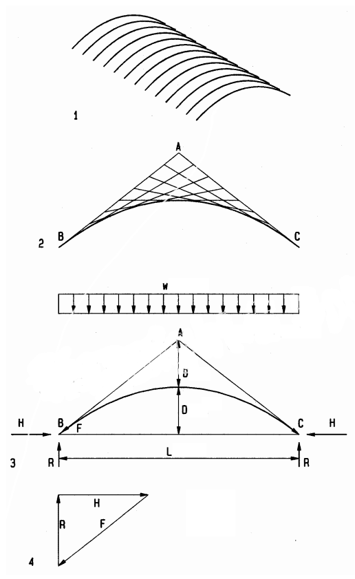
Graphic vector are powerful means to design funicular structures, like arches and  suspension roofs; providing both form and forces under uniform and random loads. 

Arch  
Assume:


1 Arch structure


2  Parabolic arch by graphic method

Process:
  Draw AB and AC (tangents of arch at supports)
  Divide tangents AB and AC into equal segments
  Lines connecting AB to AC define parabolic arch envelope 

3 Arch profile 

Process:
  Define desired arch rise D (usually D = L/5)
  Define point A at 2D above supports
  AB and AC are tangents of parabolic arch at supports
  Compute vertical reactions R = w L /2 

4  Equilibrium vector polygon at supports (force scale: 1” = 50 k)  Process:

  Draw vertical vector (reaction R)
  Complete vector polygon (diagonal vector parallel to tangent)
  Measure vectors (H = horizontal reaction, F = max. arch force)

Note:

The arch force varies from minimum at crown (equal to horizontal reaction), gradually increasing with arch slope, to maximum at the supports.

Monday, December 23, 2013

TRUSS EXAMPLE

Some trusses have bars with zero force under certain loads.  The example here has zero force in bars HG, LM, and PG under the given  load.  Under asymmetrical loads these bars would not be zero and, therefore, cannot be eliminated.  Bars with zero force have  vectors of zero length in the equilibrium polygon and, therefore, have both letters at the  same location.  

Tension and compression in truss bars can be visually verified by deformed shape (4),  exaggerated for clarity.  Bars in tension will elongate; bars in compression will shorten.  

In the truss illustrated the top chord is in compression; the bottom chord is in tension;  inward sloping diagonal bars in tension; outward sloping diagonal bars in compression.

Since diagonal bars are the longest and, therefore, more likely subject to buckling, they  are best oriented as tension bars.

1 Truss diagram
2 Force polygon
3  Tabulated bar forces (+ implies tension, - compression)
4  Deformed truss to visualize tension and compression bars
A  Bar elongation causes tension
B  Bar shortening causes compression

Tuesday, December 17, 2013

STRUCTURES - TRUSS ANALYSIS

Graphic truss analysis (Bow’s Notation) is a method to find bar forces using graphic vectors as in the following steps:

A  Draw a truss scaled as large as possible (1) and compute the reactions as for beams (by moment method for asymmetrical trusses).
 
B  Letter the spaces between loads, reactions, and truss bars.  Name bars by adjacent letters: bar BH between B and H, etc.
 
C  Draw a force polygon for external loads  and reactions in a force scale, such as  1”=10 pounds (2).  Use a large scale for accuracy.  A closed polygon with head-to-tail arrows implies equilibrium.  Offset the reactions to the right for clarity.
 
Draw polygons for each joint to find forces in connected bars.  Closed polygons
with head-to-tail arrows are in equilibrium.  Start with left joint ABHG.  Draw a
vector parallel to bar BH   through B in the polygon.  H is along BH.  Draw a vector
parallel to bar HG through G to find H at intersection BH-HG.
 
E  Measure the bar forces as vector length in the polygon.
 
F  Find bar tension and compression.  Start with direction of   load  AB  and  follow  polygon ABHGA with head-to-tail arrows.  Transpose arrows to respective bars in  the truss next to the joint.  Arrows pushing toward the joint are in compression; arrows pulling away are in tension.  Since the arrows reverse for adjacent joints,  draw them only on the truss but not on the polygon.

G  Draw equilibrium arrows on opposite bar ends; then proceed to the next joint with  two unknown bar forces or less (3).  Draw polygons for all joints (4), starting with  known loads or bars (for symmetrical  trusses half analysis is needed).

1 Truss diagram
2  Force polygon for loads, reactions, and the first joint polygon
3  Truss with completed tension and compression arrows
4  Completed force polygon for left half of truss
5  Tabulated bar forces (- implies compression)

STRUCTURES - TRUSS ANALYSIS

Monday, December 9, 2013

STRUCTURES VECTOR ANALYSIS

First used by Leonardo da Vinci, graphic vector analysis is a powerful method to analyze  and visualize the flow of forces through a structure.  However, the use of this method is restricted to statically determinate systems.  In addition to forces, vectors may represent  displacement, velocity, etc.  Though only two-dimensional forces are described here, vectors may represent forces in three-dimensional space as well.  Vectors are defined by  magnitude, line of action, and direction, represented by a straight line with an arrow and  defined as follows:

Magnitude is the vector length in a force scale, like 1” =10 k or 1 cm=50 kN
Line of Action is the vector slope and location in space
Direction is defined by an arrow pointing in the direction of action

1  Two force vectors P1 and P2 acting on a body pull in a certain direction.  The resultant R is a force with the same results as P1 and P2 combined, pulling in the  same general direction.  The resultant is found by drawing a force parallelogram [A]  or a force triangle [B].  Lines in the vector triangle must be parallel to corresponding  lines in the  vector plan [A].  The line of action of the resultant is at the intersection  of P1 / P2 in the vector plan [A].  Since most structures must be at rest it is more  useful to find the  equilibriant E that puts a set of forces in equilibrium [C].  The  equilibriant is equal in magnitude but opposite in direction to the resultant.  The  equilibriant closes a force triangle with all vectors connected head-to-tail.  The line  of action of the equilibriant is also at the intersection of P1/P2 in the vector plan [A].

2  The equilibriant of three forces [D] is found, combining interim resultant R1-2 of  forces P1 and P2 with P3 [E].  This process may be repeated for any number of  forces.  The interim resultants help to clarify the process but are not required [F].  The line of action of the equilibriant  is located at the intersection of all forces in the  vector plan [D].  Finding the equilibriant for any number of forces may be stated as  follows:

The equilibriant closes a force polygon with all forces connected head-to-tail,  and puts them in equilibrium in the force plan.

3  The equilibriant of forces without a common cross-point [G] is found in stages:   First the interim resultant R1-2 of P1 and P2 is found [H] and located at the  intersection of P1/P2 in the vector plan [G].  P3 is then combined with R1-2 to find  the equilibriant for all three forces, located at the intersection of  R1-2 with P3 in the  vector plan.  The process is repeated for any number of forces.

 STRUCTURES VECTOR ANALYSIS

Monday, December 2, 2013

STRUCTURES - BEAM REACTIONS

To find reactions for asymmetrical beams:

•  Draw an abstract beam diagram to illustrate computations
•  Use Σ M = 0 at one support to find reaction at other support
•  Verify results for vertical equilibrium


1 Floor framing
2  Abstract beam diagram

Support reactions:


Alternate method (use uniform load directly)


1  Simple beam with point loads


2  Beam with overhang and point loads 


3  Beam with uniform load and point load (wall)


Monday, November 25, 2013

STRUCTURES - SUPPORT SYMBOLS

The diagrams show common types of support at left and related symbols at right.  In  addition to the pin and roller support described above, they also include fixed-end  support (as used in steel and concrete moment frames, for example).


Monday, November 18, 2013

SUPPORTS TYPES - STRUCTURES

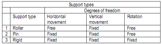
For convenience, support types are described  for beams, but apply to other horizontal  elements, like trusses, as well.  The type of support affects analysis and design, as well  as performance.  Given the three equations of statics defined above, ΣH=0, ΣV=0, and  ΣM=0, beams with three unknown reactions are considered determinate  (as described  below) and can be analyzed by the three static equations.  Beams with more than three  unknown reactions are considered  indeterminate and cannot be analyzed by the three  static equations alone.  A beam with two pin supports (1 has four unknown reactions, one  horizontal and one vertical reaction at each support.  Under load, in addition to bending,  this beam would deform like a suspended cable in tension, making the analysis more  complex and not possible with static equations.

By contrast, a beam with one pin and one roller support (2) has only three unknown  reactions, one horizontal and two vertical.  In bridge structures such supports are quite  common.  To simplify analysis, in building structures this type of support may be  assumed, since supporting walls or columns usually are    flexible enough to simulate the  same behavior as one pin and one roller support.  The diagrams at left show for each  support on top the physical conditions and below the symbolic abstraction.

Beam with fixed supports at both ends subject to bending and tension
2  Simple beam with one pin and one roller support subject to bending only
3  Beam with flexible supports, behaves like a simple beam

Simple beams, supported by one pin and one roller, are very common and easy to  analyze.  Designations of roller- and pin supports are used to describe the structural  behavior assumed for analysis, but do not always reflect the actual physical support.  For  example, a pin support is not an actual pin but a support that resists horizontal and  vertical movement but allows rotation.  Roller supports may consist of Teflon or similar  material of low friction that allows horizontal movement like a roller.


Monday, November 11, 2013

BRACED FRAMES - STRUCTURES

Braced frames resist gravity load in bending and axial compression, and lateral load in axial compression and tension by triangulation, much like trusses.  The triangulation results in greater stiffness, an advantage to resist wind load, but increases seismic  forces, a disadvantage to resist earthquakes.  Triangulation may take several  configurations, single diagonals, A-bracing, V-bracing, X-bracing, etc., considering both  architectural and structural criteria.  For example, location of doors may be effected by  bracing and impossible with X-bracing.  Structurally, a single diagonal brace is the  longest, which increases buckling tendency  under compression.  Also the number of  costly joints varies: two for single diagonals, three for A- and V-braces, and five joints for  X-braces.  The effect of bracing to resist load is visualized through amplified deformation  as follows:

1  Single diagonal portal under gravity and lateral loads
2  A-braced portal under gravity and lateral load
3  V-braced portal under gravity and lateral load
4  X-braced portal under gravity and lateral load
5  Braced frame building without and with lateral load

Note: deformations and forces reverse under reversed load


Monday, November 4, 2013

MOMENT FRAMES - STRUCTURES

Moment frames resist gravity and lateral load in bending and compression. They are derived from post-and beam portals with moment resisting beam to column connections (for convenience refered to as moment frames and moment joints).  The effect of moment joints is that load applied to the beam will rotate its ends and in turn rotate the attached columns.  Equally, load applied to columns will rotate their ends and in turn  rotate the beam.  This mutual interaction makes moment frames effective to resist lateral load with ductility. Ductility is the capacity to deform without breaking, a good property to resist earthquakes, resulting in smaller seismic forces than in shear walls and braced frames.  However, in areas with prevailing wind load, the greater stiffness of shear walls and braced frames is an advantage,  The effect of moment joints to resist loads is  visualized through amplified deformation as follows:

1  Portal with pin joints collapses under lateral load
2  Portal with moment joints at base under lateral load
3  Portal with moment beam/column joints under gravity load
4  Portal with moment beam/column joints under lateral load
5  Portal with all moment joints under gravity load
6  Portal with all moment joints under lateral load
7  High-rise moment frame under gravity load
8  Moment frame building under lateral load
I  Inflection points (zero bending between negative and positive bending

Note: deformations reverse under reversed load


Monday, October 28, 2013

CANTILEVERS STRUCTURES

Cantilevers resist lateral load primarily in bending.  They may consist of single towers or  multiple towers.  Single towers act much like trees and require large footings like tree  roots to resist overturning.  Bending in cantilevers increases from top down, justifying  tapered form in response.

1  Single tower cantilever
2  Single tower cantilever under lateral load
3  Twin tower cantilever
Twin tower cantilever under lateral load
5  Suspended tower with single cantilever
6  Suspended tower under lateral load

Monday, October 21, 2013

Shear Walls Systems

As the name implies, shear walls resist lateral load in shear.  Shear walls may be of wood, concrete or masonry.  In the US the most common material for low-rise  apartments is light-weight wood framing with plywood or particle board sheathing. Framing studs, spaced 16 or 24 inches, support gravity load and sheathing resists lateral  shear.  In seismic areas concrete and masonry shear walls must be reinforced with steel  bars to resist lateral shear.

1  Wood shear wall with plywood sheathing
2  Light gauge steel shear wall with plywood sheathing
3  Concrete shear wall with steel reinforcing
4  CMU shear wall with steel reinforcing
5  Un-reinforced brick masonry (not allowed in seismic areas)
8  Two-wythe brick shear wall with steel reinforcing


Monday, October 14, 2013

VERTICAL SYSTEMS STRUCTURES

Vertical systems transfer the load of horizontal systems from roof to foundation, carrying  gravity and/or lateral load.  Although they may  resist gravity or lateral load only, most  resist both, gravity load in compression, lateral load in shear.  Walls are usually designed  to define spaces and provide support, an appropriate solution for apartment and hotel  buildings.  The four systems are:

1  Shear walls (apartments / hotels)
2  Cantilever (Johnson Wax tower by F L Wright)
Moment frame
4  Braced frame


A  Concrete moment resistant joint Column re-bars penetrate beam and beam re-bars penetrate column)  B  Steel moment resistant joint (stiffener plates between column flanges resist beam flange stress)


Tuesday, October 8, 2013

VERTICAL STRUCTURES

Vertical elements

Vertical elements transfer load from roof to foundation, carrying gravity and/or lateral  load.  Although elements may resist only gravity or only lateral load, most are designed to  resist both.  Shear walls designed for both gravity and lateral load may use gravity dead  load to resist overturning which is most important for short walls.  Four basic elements  are used individually or in combination to resist gravity and lateral loads

1  Wall under gravity load
2  Wall under lateral load (shear wall)
3  Cantilever under gravity load
4  Cantilever under lateral load
5  Moment frame under gravity load
6  Moment frame under lateral load
7  Braced frame under gravity load
9  Braced frame under lateral load

Monday, September 30, 2013

FUNICULAR STRUCTURES

The funicular concept can be best described  and visualized with cables or chains,  suspended from two points, that adjust their form for any load in tension.  But funicular  structures may also be  compressed like arches. Yet, although funicular tension  structures adjust their form for pure tension under any load, funicular compression  structures may be subject to bending in addition  to compression since their form is rigid  and not adaptable.  The funicular line for tension and compression are inversely identical;  the form of a cable becomes the form of an arch upside-down.  Thus funicular forms may  be found on tensile elements.

1  Funicular tension triangle under single load
2  Funicular compression triangle under single load
3  Funicular tension trapezoid under twin loads
4  Funicular compression trapezoid under twin loads
5  Funicular tension polygon under point loads
6  Funicular compression polygon under point load
7  Funicular tension parabola under uniform load
8  Funicular compression parabola under uniform load

FUNICULAR STRUCTURES

Vault
IBM traveling exhibit by Renzo Piano A series of trussed arches in linear extrusion form a vault space  The trussed arches  consist of wood bars with metal connectors for quick assembly and disassembly as  required for the traveling exhibit.  Plastic  panels form the enclosing skin,  The trussed  arches provide depth and rigidity to accommodate various load conditions


Suspension roof
Exhibit hall Hanover by Thomas Herzog


Monday, September 23, 2013

STRUCTURES - TRUSSES

Trusses support load much like beams, but for longer spans.  As the depth and thus dead weight of beams increases with span they become increasingly inefficient, requiring  most capacity to support their own weight rather than imposed live load.  Trusses replace  bulk by triangulation to reduce dead weight.

1  Unstable square panel deforms under load. Only triangles are intrinsically stable polygons
2  Truss of triangular panels with inward sloping diagonal bars that elongate in tension under load (preferred configuration)
3  Outward sloping diagonal bars compress (disadvantage)
4  Top chords shorten in compression Bottom chords elongate in tension under gravity load
Gable truss with top compression and bottom tension


Warren trusses
Pompidou Center, Paris by Piano and Rogers


Prismatic trusses
IBM Sport Center by Michael Hopkins
(Prismatic trusses of  triangular cross section provide rotational resistance)


Space trusses 
square and triangular plan

Note: Two way space trusses are most effective if  the spans in the principle directions are  about equal, as described for two-way slabs above.  The base modules of trusses should  be compatible with plan configuration (square, triangular, etc.)

Monday, September 16, 2013

HORIZONTAL STRUCTURES

Horizontal systems come in two types: one way and two way. Two way systems are only  efficient for spaces with about equal span in both directions; as described below.  The  diagrams here show one way systems at left and two way systems at right

1  Plywood deck on wood joists
2  Concrete slab on metal deck and steel joists
3  One way concrete slab
4  One way beams
5  One way rib slab
6  Two way concrete plate
7  Two way concrete slab on drop panels
8  Two way concrete slab on edge beams
9  Two way beams  
10  Two way waffle slab
11 Deflection ∆ for span length L1
12 Deflection ∆=16 due to double span L2 = 2 L1

Note: Deflection increases with the fourth power of span.  Hence for double span deflection  increase 16-fold.. Therefore two way systems over rectangular plan are ineffective  because elements that span the short way control deflection and consequently have to  resist most load and elements that span the long way are very ineffective.

Monday, September 9, 2013

Rupture Length (material properties, i.e., structural efficiency)

Rupture length is the maximum length a bar of constant cross section area can be  suspended without rupture under its weight in tension (compression for concrete & masonry).

Rapture length defines material efficiency as strength / weight ratio:

R = F / λ

R = rupture length
F = breaking strength
λ = specific gravity (self weight) 

Rupture length, is of particular importance for long-span structures.  The depth of  horizontal span members increases with span.  Consequently the weight also increases  with span.  Therefore the capacity of material to span depends on both its strength and  weight.  This is why lightweight material, such as glass fiber fabrics are good for long- span structures.  For some material, a thin line extends the rupture length to account for  different material grades.

The graph data is partly based on a study of the Light weight Structures Institute, University Stuttgart, German.