Based on the relatively good ground conditions, a 150 mm concrete slab on 150 mm of hardcore will initially be assumed.
 |
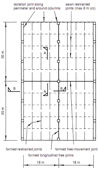
| Fig. 11.49 Floating slab design example – plan showing movement joints. |
Joints and reinforcement for shrinkage purposes
The slab is intended to be constructed using the long strip method. The slab will be cast in 60 m × 4.5 m strips, in an alternate bay sequence, as shown in Fig. 11.49. The strips being sawn into 6 m square panels as shown is practicable when the concrete is strong enough to avoid damage to arrises and no later than 24 h after placing. If an A393 mesh is to be used, one formed free-movement joint along the 60 m length of the building will be appropriate.
Similarly, a formed free-movement joint should be provided in the longitudinal direction. The various reinforcement and joint details are shown in Fig. 11.50. Spanning over local depression
 |
| Fig. 11.50 Floating slab design example – movement joint details. |
(1) Select a diameter for a local depression from Table 11.4.
Modify it if required to take into account the thickness of any compacted granular material/hardcore below
the slab, as per Fig. 13.4 (a).
In this example, with the sub-grade comprising a consistent medium dense sand, a design span of 0.95 m will be used.
(2) Calculate the loads acting over a depression located at an unsupported slab corner, as per Fig. 11.51. (This is the worst case location for a depression.)
 |
| Fig. 11.51 Floating slab design example – designing for local depression. |
In this example, the ultimate foundation loads due to slab self-weight and imposed load of 25 kN/m2 is given by
No significant point loads are assumed to act in this particular example.
(3) Calculate the cantilever moment per metre width adjacent to this depression from Fig. 11.51.
An A mesh is proposed, giving a two-way moment of
(4) Calculate the corresponding area of mesh reinforcement required.
An A142 mesh will therefore be satisfactory.
Normally this reinforcement, calculated for the worst case condition at a slab corner, would be provided throughout the slab. In situations where this results in an excessive amount of reinforcement, a separate calculation can be carried out for a depression located in the middle of the slab.


No comments:
Post a Comment